Traffic detection system and communication-quality monitoring system on a network

a traffic detection system and communication quality technology, applied in the direction of network topologies, data switching by path configuration, electrical devices, etc., can solve the problems of inability to monitor voice quality by using the described technique, preventing protocol analysis, and affecting the communication quality of the internet telephon

Inactive Publication Date: 2007-03-15
NEC CORP
View PDF12 Cites 31 Cited by
  • Summary
  • Abstract
  • Description
  • Claims
  • Application Information

AI Technical Summary

Benefits of technology

[0012] It is another object of the present invention to provide a communication-quality monitoring system which is capable of detecting a subject traffic from encrypted traffics flowing on a network without decrypting the encrypted traffic and monitoring the communication quality of the subject traffic component.

Problems solved by technology

It is known however that the internet telephone suffers from degradation in the communication quality such as a delay or disappearance of the packets within the IP network.
In the WLAN communication system however, the WLAN data transferred through a communication path using the TKIP as the encryption protocol cannot be decrypted to thereby preclude the protocol analysis, because the encryption key is dynamically updated.
That is, WLAN communication system does not allow the voice traffic to be detected from the encrypted WLAN traffic, and thus the monitoring of the voice quality by using the described technique is impossible.
This problem is common to encrypted communication paths using the IPsec as the encryption protocol.
However, since the packet analysis is impossible with respect to the encrypted packets, as described above, the VoIP packets cannot be separated from the other packets, whereby it is impossible to monitor the voice quality in the WLAN traffic or the traffic of the communication path encrypted using the encryption protocol.

Method used


Image

  • Traffic detection system and communication-quality monitoring system on a network
  • Traffic detection system and communication-quality monitoring system on a network
  • Traffic detection system and communication-quality monitoring system on a network

Examples


Embodiment Construction

[0037] Now, the present invention is more specifically described with reference to accompanying drawings, wherein similar constituent elements are designated by similar reference numerals.

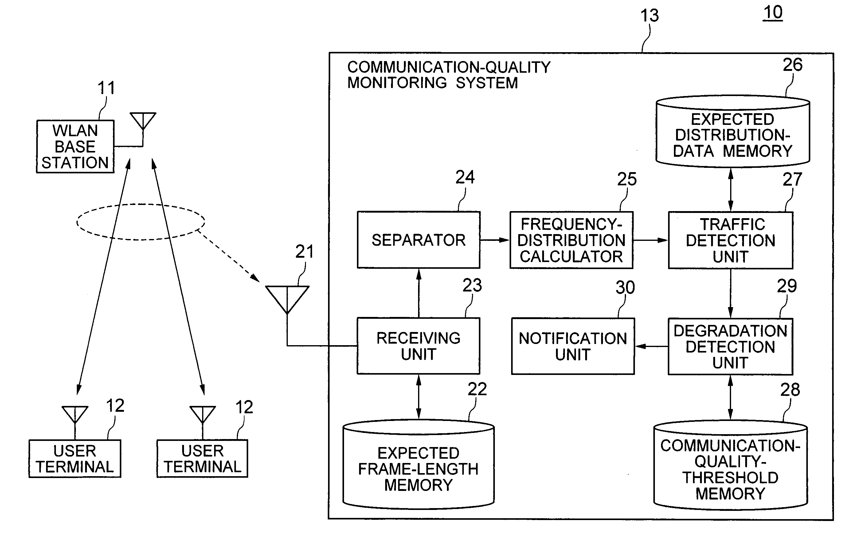
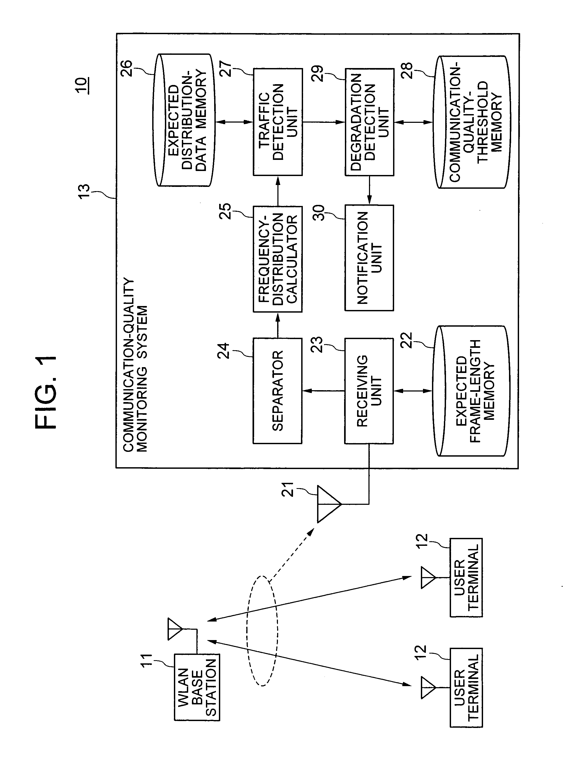
[0038]FIG. 1 shows a communication system including a communication-quality monitoring system according to a first embodiment of the present invention. The communication system, generally designated by numeral 10, includes a plurality of WLAN base stations 11, a plurality of user terminals 12 for use in a cellular phone system, and a communication-quality monitoring system 13. The WLAN base stations 11 establish a communication with the user terminals 12 by using an encrypted wireless communication. The user terminals 12 may be personal computers, for example, on which a variety of programs run including voice application programs, such as an IP telephone program. Thus, the traffics between the WLAN base stations 11 and the user terminals 12 include voice traffics generated by the voice applicatio...


PUM


Abstract

A communication-quality monitoring system includes a receiving unit for receiving packets to detect packets of a traffic, a frequency-distribution calculator for calculating frequency distribution of the arrival times of the received packets, and a degradation detection unit for detecting degradation of communication quality in the network by comparing statistic parameters of the peak in the frequency distribution against thresholds of the parameters. The parameters include a dispersion, standard deviation, half-power breadth and peak power of the peak in the distribution diagram.

Description

BACKGROUND OF THE INVENTION [0001] (a) Field of the Invention [0002] The present invention relates to a traffic detection system on a network and, more particularly, to a technique for detecting a subject traffic flowing on a network. The present invention also relates to a communication-quality monitoring system. [0003] (b) Description of the Related Art [0004] Recently, a specific communication service attracts a higher attention, which allows transmission / reception of a voice communication via the IP network while packetizing voice data by using a voice application program such as voice over internet protocol (VoIP). This communication service is now remarkably growing in the form of the “internet telephone”. It is known however that the internet telephone suffers from degradation in the communication quality such as a delay or disappearance of the packets within the IP network. [0005] Patent Publications JP-2002-232475 and -2004-165818 describe a technique for monitoring the com...

Claims


Application Information

Patent Timeline
Patent Type & Authority Applications(United States)
IPC IPC(8): H04Q7/20H04L12/28H04W24/00H04W24/08H04W84/12
CPCH04L43/026H04L43/16H04L43/062H04L43/045H04L12/56H04L41/14H04L41/142H04L43/00
Inventor KITAMURA, TSUTOMUOKABE, TOSHIYA
Owner NEC CORP
Why Eureka
Try Eureka