Methods and apparatus for assisted aspiration

a technology of aspiration catheter and aspiration catheter, which is applied in the direction of multi-lumen catheter, catheter, intravenous device, etc., can solve the problems of affecting the sealing of materials, and achieve the effect of reducing friction and facilitating the introduction of blood vessels

Inactive Publication Date: 2007-03-15
FOX HOLLOW TECH
View PDF28 Cites 106 Cited by
  • Summary
  • Abstract
  • Description
  • Claims
  • Application Information

AI Technical Summary

Benefits of technology

This patent describes new types of aspiration catheters used to remove materials from bodily spaces like blood vessels. These catheters have several features: they are designed with a special opening called an aspiration port, through which material can be removed when sucked out; they often have a separate channel for introducing another device (like a balloon) into the space before removing the material; and sometimes they even have a place to inject medicine during the procedure. One important improvement described in this patent involves modifying the design of the aspiration port itself to prevent any partial or full blocking of the removal process. This modification can involve adding something physical inside or outside of the port, like a wire or a roller, that breaks up the material being removed. Overall, these improvements make the aspiration catheters better able to safely and effectively clear blockages in bodily spaces.

Problems solved by technology

The technical problem addressed by this patent is how to design catheters and systems that can effectively remove blockages from blood vessels and other bodily spaces without causing damage or discomfort to patients.

Method used


Image

  • Methods and apparatus for assisted aspiration
  • Methods and apparatus for assisted aspiration
  • Methods and apparatus for assisted aspiration

Examples


Embodiment Construction

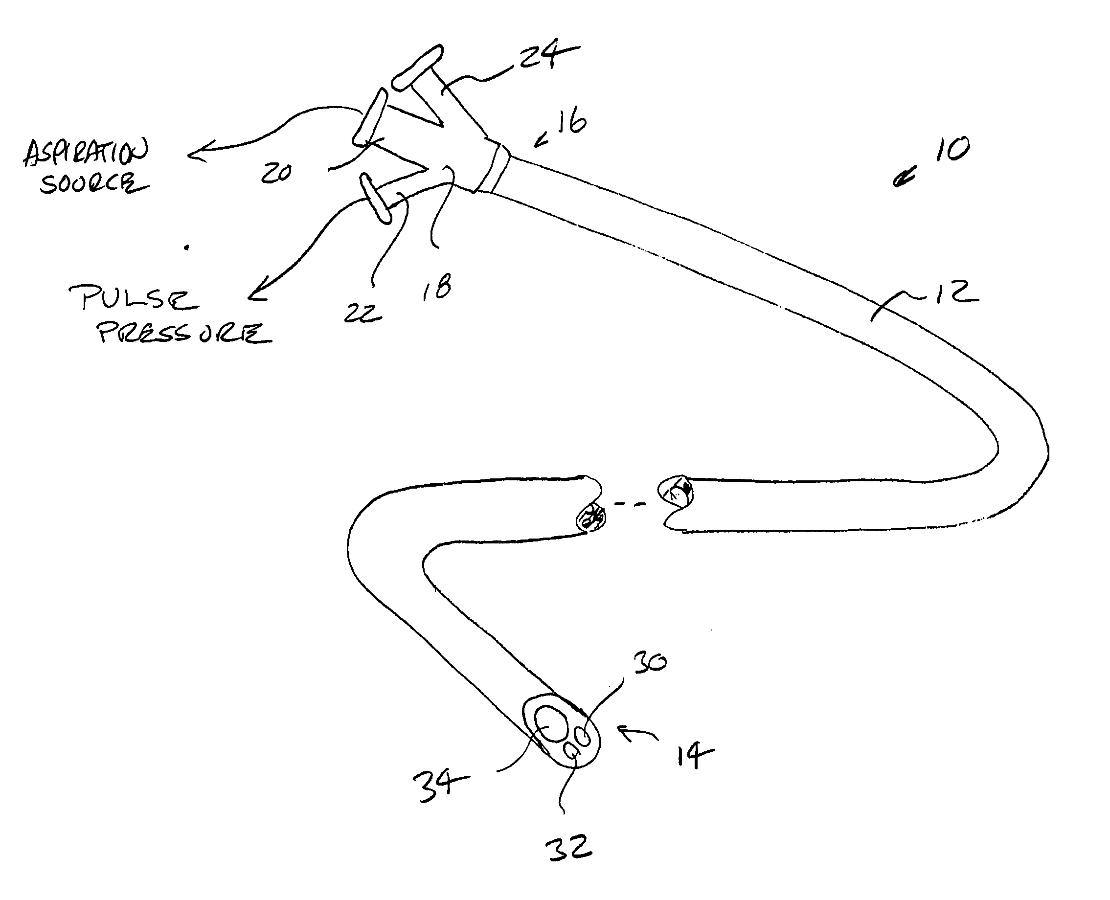
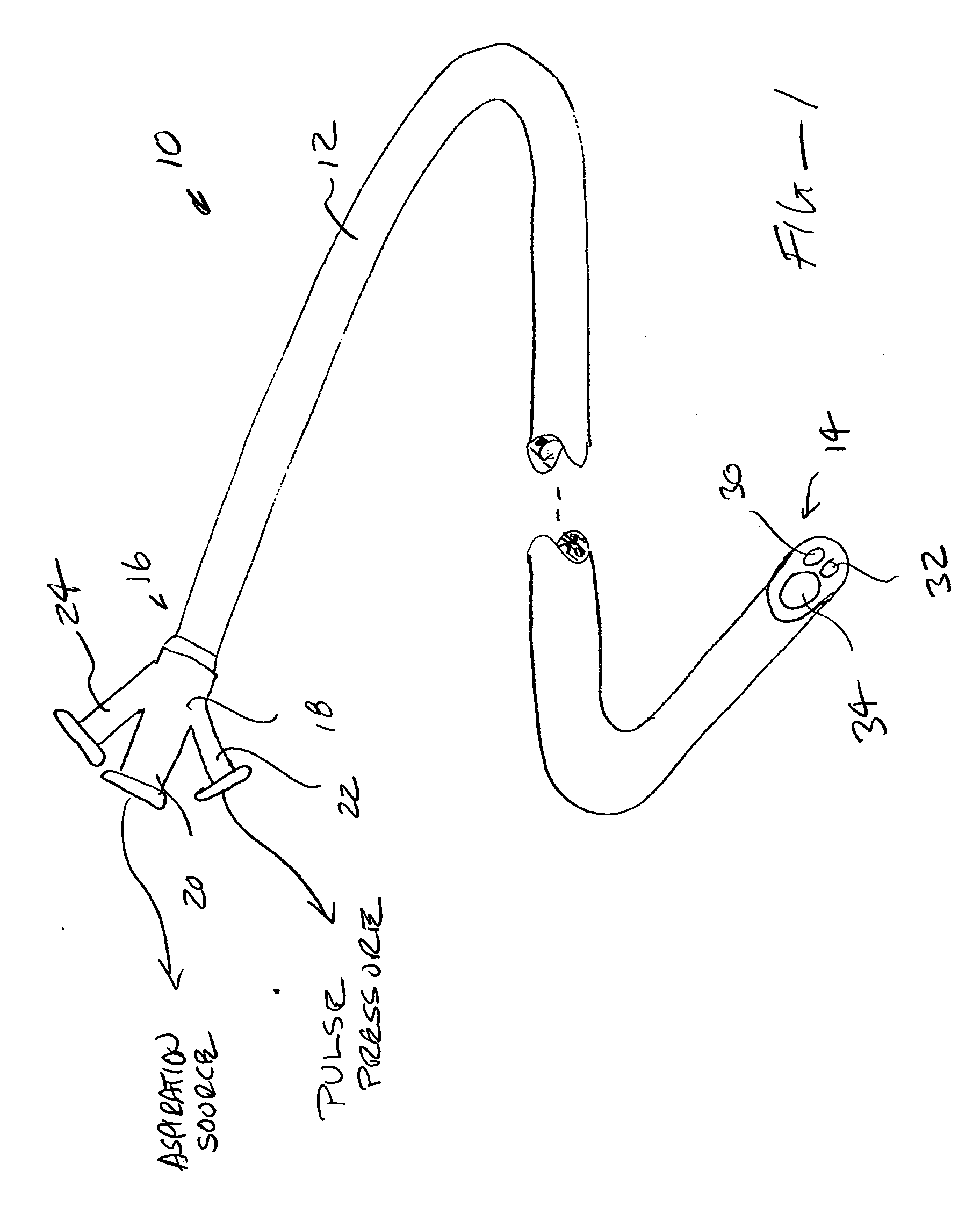
[0032] An aspiration catheter 10 constructed in accordance with the principles of the present invention comprises a catheter body 12 having a distal end 14 and proximal end 16. A proximal hub 18 is attached to the proximal end 16 of the catheter body 12 and includes an aspiration connector 20, a pulse lumen connector 22, and a guidewire connector 24. The aspiration connector 20 will be adapted to connect to a vacuum source, typically operating at from minus 10 mmHg to minus 760 mmHg. A pulse lumen connector, which is optional, may be attached to a pressure source, typically operating from positive 10 mmHg to positive 760 mmHg.

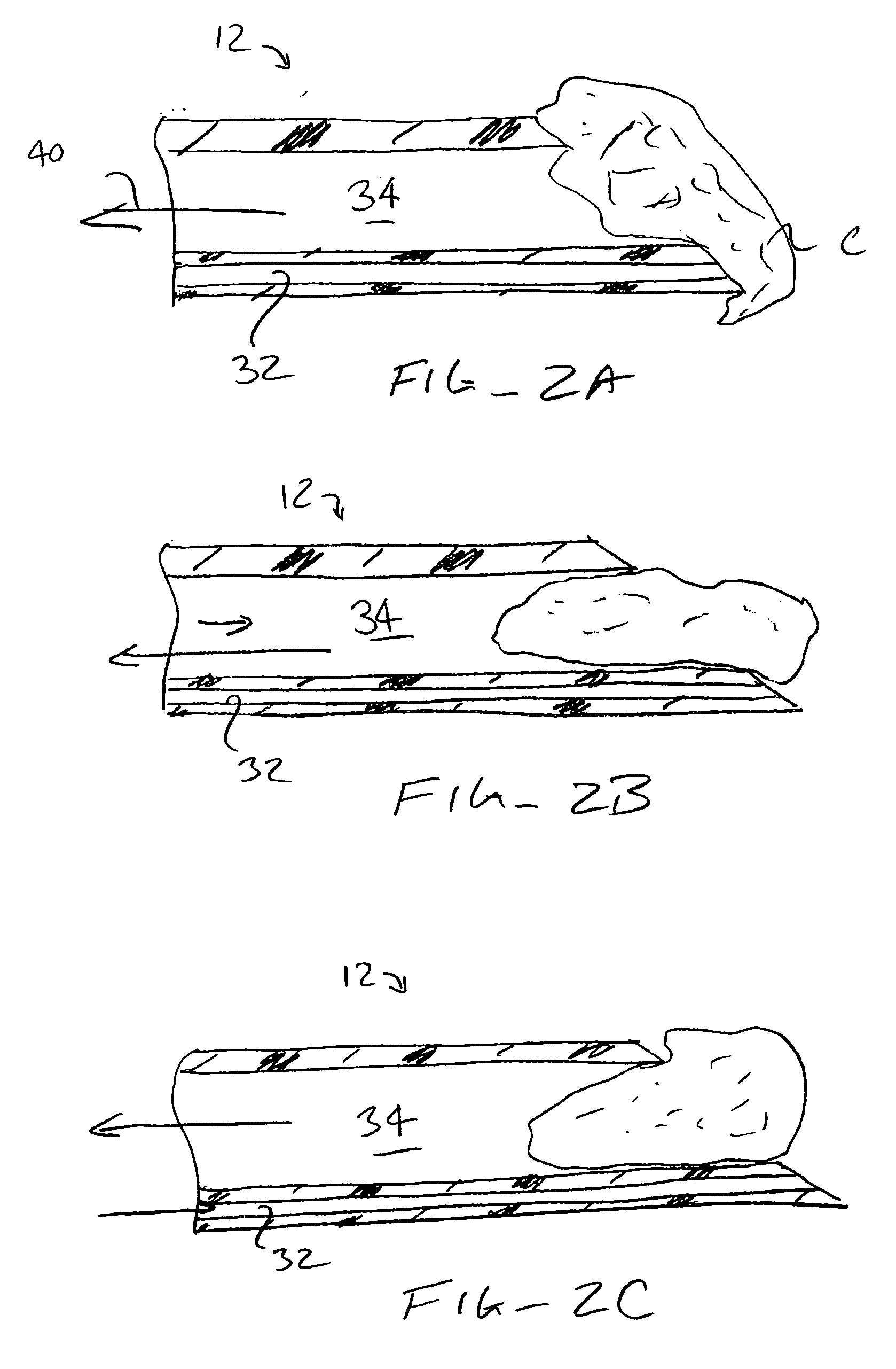
[0033] The guidewire connection 24 allows the guidewire to enter guidewire lumen 30 and the catheter body 12, while the pulse pressure connector 22 connects to the pulse pressure lumen 32. The aspiration connector 20 connects to the central aspiration lumen 34. In this way, while the aspiration lumen 34 is connected to the aspiration source, the guidewire can ...


PUM


Abstract

An aspiration catheter comprises a catheter body having an aspiration lumen therethrough. The distal opening of the aspiration lumen can be modified in various ways or can have the addition of structure in order to disrupt sealing between the port and material being aspirated. Examples of modifications include slots, castellations, zig-zag features, and other geometries which resist sealing of aspirated material. Blades, rollers, vibrating elements, and other structures may be provided within or around the distal end of the aspiration lumen in order to dislodge and disrupt aspirated material which can seal against the opening.

Description


Claims


Application Information

Patent Timeline
Owner FOX HOLLOW TECH
Why Eureka
Try Eureka