Optoelectronic reader and method for reading machine-readable symbols

a technology of machine-readable symbols and optoelectronic readers, applied in the field of automatic data collection (adc), can solve the problems of limited range and/or depth of field, imagers with auto-focus lens systems suffering from delays associated with focusing imager lenses, etc., and achieve the effect of improving drawing legibility

Inactive Publication Date: 2007-03-22
INTERMEC IP
View PDF6 Cites 15 Cited by
  • Summary
  • Abstract
  • Description
  • Claims
  • Application Information

AI Technical Summary

Problems solved by technology

Imagers advantageously eliminate moving parts, and allow high reading speeds at relatively low cost, but may have limited range and / or depth-of-field.
However, imagers with auto-focus lens systems suffer from delays associated with focusing the imager lens.

Method used


Image

  • Optoelectronic reader and method for reading machine-readable symbols
  • Optoelectronic reader and method for reading machine-readable symbols
  • Optoelectronic reader and method for reading machine-readable symbols

Examples


Embodiment Construction

[0022] In the following description, certain specific details are set forth in order to provide a thorough understanding of various disclosed embodiments. However, one skilled in the relevant art will recognize that embodiments may be practiced without one or more of these specific details, or with other methods, components, materials, etc. In other instances, well known structures associated with optoelectronic readers such as barcode readers and methods for reading machine-readable symbols such as barcode symbols, area or matrix code symbols and / or stacked code symbols have not been shown or described in detail to avoid unnecessarily obscuring descriptions of the embodiments.

[0023] Unless the context requires otherwise, throughout the specification and claims which follow, the word “comprise” and variations thereof, such as, “comprises” and “comprising” are to be construed in an open, inclusive sense, that is as “including, but not limited to.”

[0024] Reference throughout this spe...


PUM


Abstract

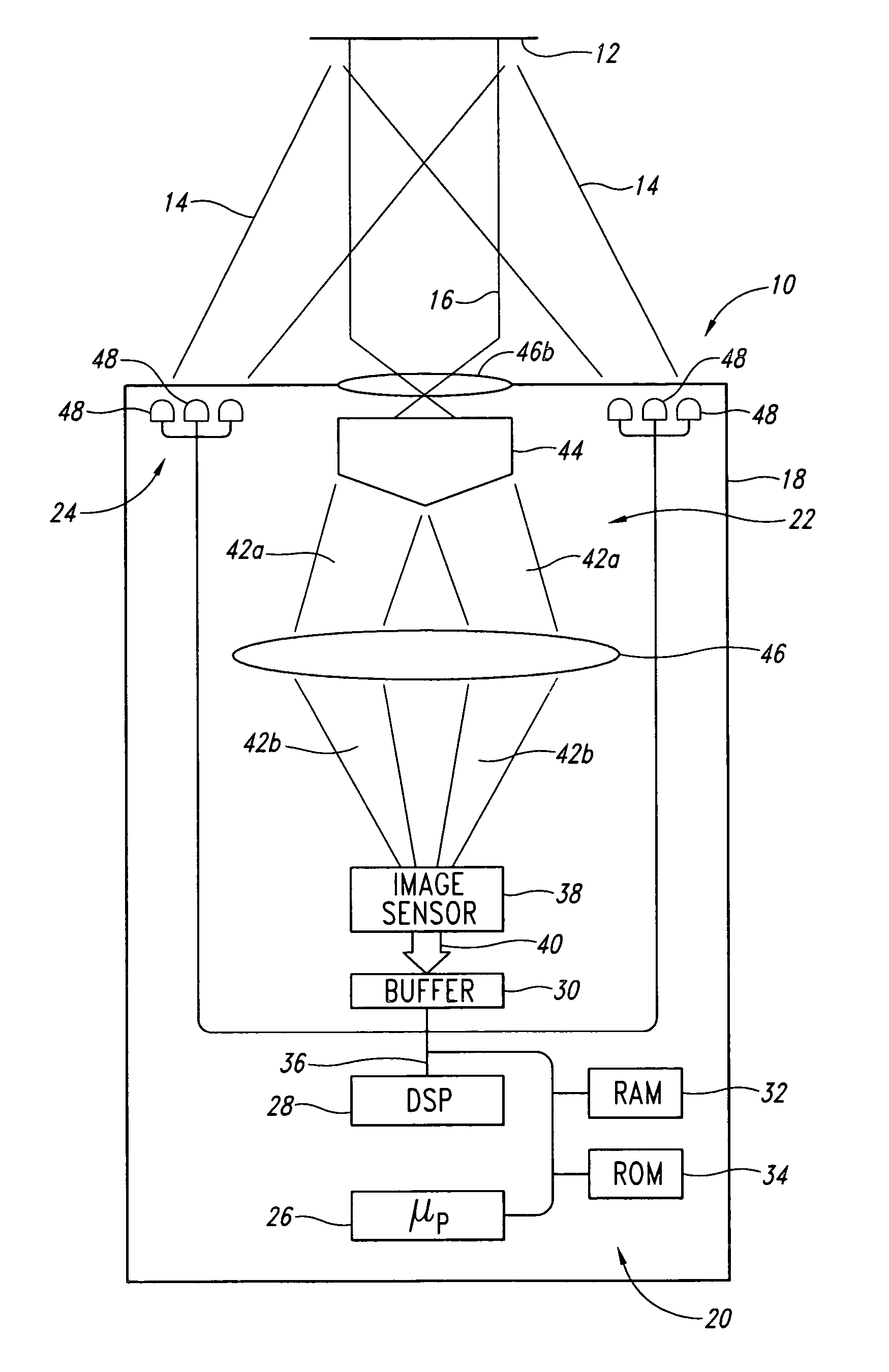
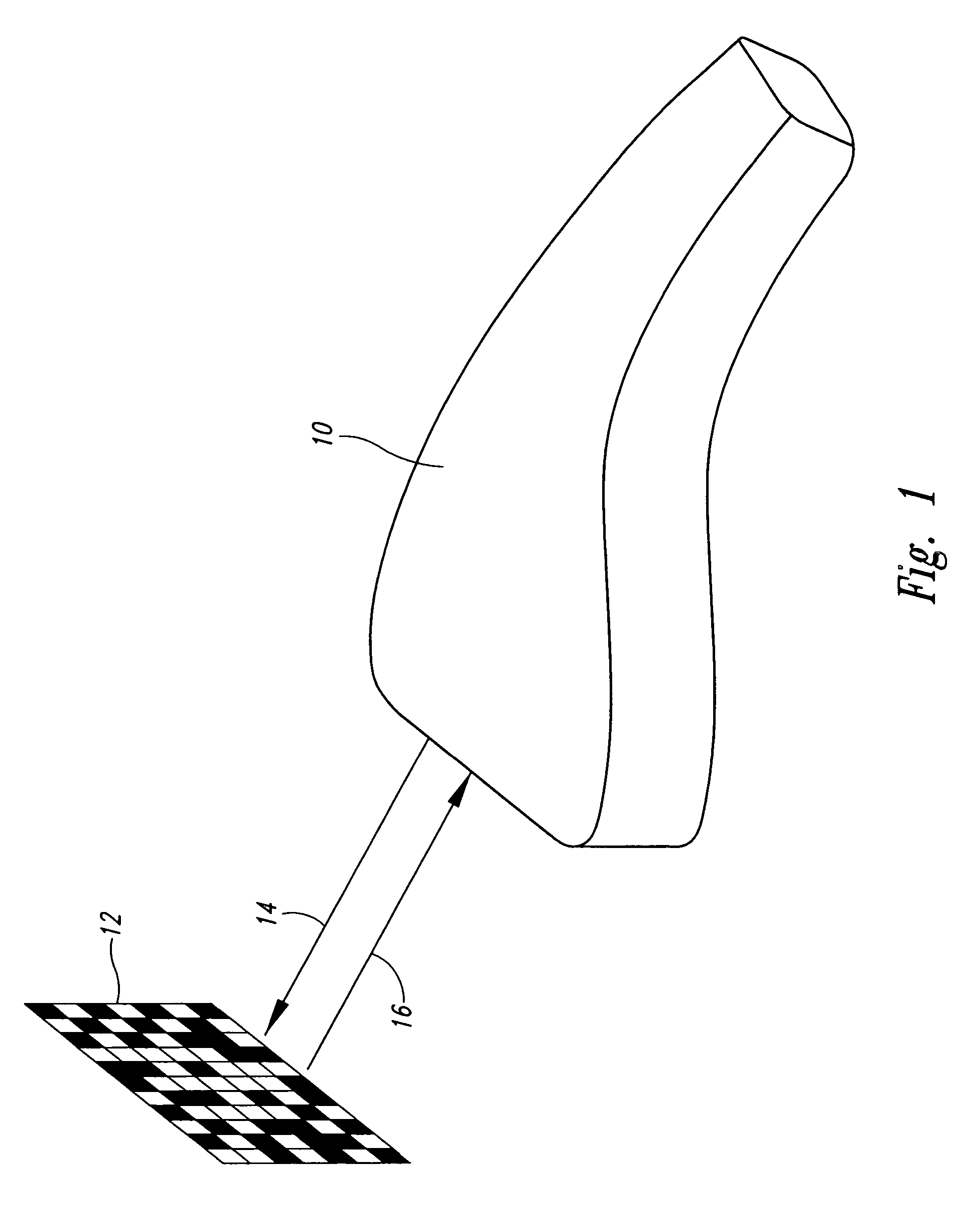
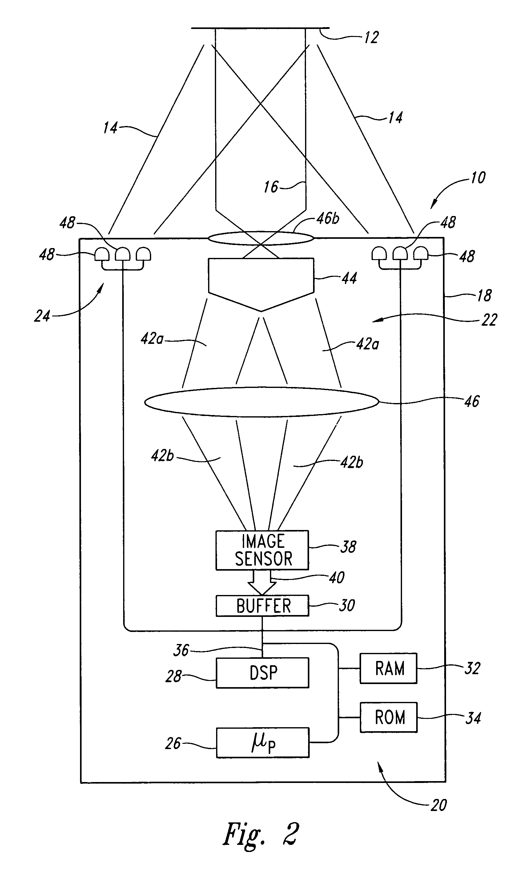
An optoelectronic reader for reading machine-readable symbols such as barcode symbols employs an optical assembly to focus a non-Gaussian image on an image sensor. The optical assembly may include a substantially diffraction free optical element, such as an annular slit aperture or a conical lens element, for example a conical refracting surface or axicon lens element.

Description

CROSS-REFERENCE TO RELATED APPLICATION [0001] This application claims the benefit under 35 U.S.C. § 119(e) of U.S. Provisional Patent Application No. 60 / 719,625, filed Sep. 21, 2005.BACKGROUND OF THE INVENTION [0002] 1. Field of the Invention [0003] This disclosure generally relates to the automatic data collection (ADC) field, and more particularly to optoelectronic readers operable to read machine-readable symbols, for example barcode symbols, area or matrix code symbols and / or stack code symbols. [0004] 2. Description of the Related Art [0005] Optoelectronic readers for reading machine-readable symbols are generally categorized into two groups: 1) moving beam devices commonly referred to as scanners (e.g., laser scanners), and 2) fixed beam devices commonly referred to as imagers (e.g., CCD imagers). Each group has its own relative advantages. [0006] Moving beam devices typically move or scan a light across a target. For example, a scanner may employ a laser diode and a mechanism...

Claims


Application Information

Patent Timeline
Patent Type & Authority Applications(United States)
IPC IPC(8): G06K7/10
CPCG06K7/10732G06K7/10722
Inventor HEINRICH, HARLEY K.
Owner INTERMEC IP
Why Eureka
Try Eureka