
Signaling safety system

a safety system and signal technology, applied in the direction of optical signals, cycle equipment, vehicle components, etc., can solve the problems of many drivers not being able to see motorcycles/bicycle extreme danger of riding motorcycles/bicycles on the road, and difficult to see motorcycles/bicycles

Inactive Publication Date: 2007-03-22
PERKINS BARRY +1
View PDF13 Cites 63 Cited by
  • Summary
  • Abstract
  • Description
  • Claims
  • Application Information

AI Technical Summary

Benefits of technology

"The present invention is a signaling system for motorcycles or bicycles that provides a light indication to other motorists. The system includes an indication mechanism that is attached to the rider's garment and has LED arrays. The system also includes a wireless radio receiver and a signal interface that intercepts signals from the motorcycle's light system. When the signal interface detects a signal, it sends a signal to the wireless radio transmitter, which then sends the signal to the indication mechanism, which illuminates the appropriate LED array to provide a light indication to warn other motorists. The indication mechanism may be worn by a cyclist and may detect braking actions or deceleration of the bicycle. The technical effect of this invention is to provide a safer way for cyclists to be seen and to alert other motorists of their actions to prevent accidents."

Problems solved by technology

However, although popular, there is extreme danger associated with riding motorcycles and bicycles on the road.
One of the greatest problems associated with motorcycles and bicycles is the inability of many drivers to see the motorcycles / bicycles on the road.
Because of their size, motorcycles / bicycles are oftentimes difficult to see.
Additionally, because motorcycles have signaling lights which are smaller than conventional automobiles, drivers do not observe motorcycles signals when stopping, slowing, or indicating a turn.
However, Harris does not teach or suggest a signaling system affixed to a garment of the rider.
Harris suffers from the disadvantage of providing a signaling system to a modified helmet.
Such modifications on a helmet are currently not permitted by federal law.
Additionally, Harris does not teach or suggest a system for indicating a turn.
However, Lu does not teach or suggest a signaling device worn on a jacket of the rider.
Additionally, Lu does not teach or suggest the use of a wireless radio telecommunications link to the motorcycle.
Likewise, Lu does not disclose a device providing a turn signal indicator.
Lu suffers from the disadvantage of utilizing a complex device to interface with the braking system by requiring the use of a device providing a flux detector, thereby increasing the cost and complexity of the device.
However, Fuentes does not disclose an interface for transmitting the brake or turn signal indication to the garment.
Additionally, Fuentes does not teach or suggest a safety garment or accessory for use on a bicycle.
However, Musselman does not teach or suggest utilizing a wireless radio communications link to a light indication device worn by the cyclist.
Additionally, Tigwell does not teach or suggest any interface with a motorcycle (i.e., no wireless communications).
Additionally, Gebelein does not teach or suggest utilizing an RF wireless communications link.
However, Whiting does not teach or suggest the use of insulation displacement connectors (IDCs) to interface with the wiring system.
In addition, Whiting does not teach or suggest a lighting system mounted to the back of the motorcyclist.
However, Stewart does not teach or suggest utilizing an RF wireless communications link.
However, Restauro does not teach or suggest a wireless radio communications link between the garment and the motorcycle.
Additionally, Restauro does not teach or suggest how the wiring system is interfaced.
Additionally, Spearing does not disclose how the light system interfaces with the wiring system of the motorcycle.
De Silva suffers from a major disadvantage in that the lights must be actuated by the person manipulating controls on the shoulder straps of the garment.
However, Moore does not teach or suggest mounting a light array on the back of a garment.
Additionally, Moore does not teach or suggest utilizing the RF link to communicate with a sensing device located on the brakes of a bicycle.
In regards the patents disclosing lights located on helmets worn by riders, these patents suffer from the fact that a device that is attached to helmets is against current federal regulations.
Furthermore, these patents do not teach or suggest affixing the lights to directly to garments, which provides a surface area which is far more visible to other motorists.
None of these patents which disclose lights on the helmet discuss the problems associated with attaching devices to helmets or the deterioration of the structural integrity of the helmet.
In regards to those patents which include wires connecting a garment to the motorcycle, there are also significant safety concerns.
For example, wire related injuries may result during an accident if a wire is attached between the garment and the motorcycle.
Finally, none of the patents disclose a simple way of interfacing with the motorcycle wiring system.
Existing prior art references merely disclose splicing wires, which is complicated, increases the danger of electrical problems through modification of the wiring system of the motorcycle, and increases the cost of utilizing professional mechanics to install the interface.

Method used


Image

  • Signaling safety system
  • Signaling safety system
  • Signaling safety system

Examples


Embodiment Construction

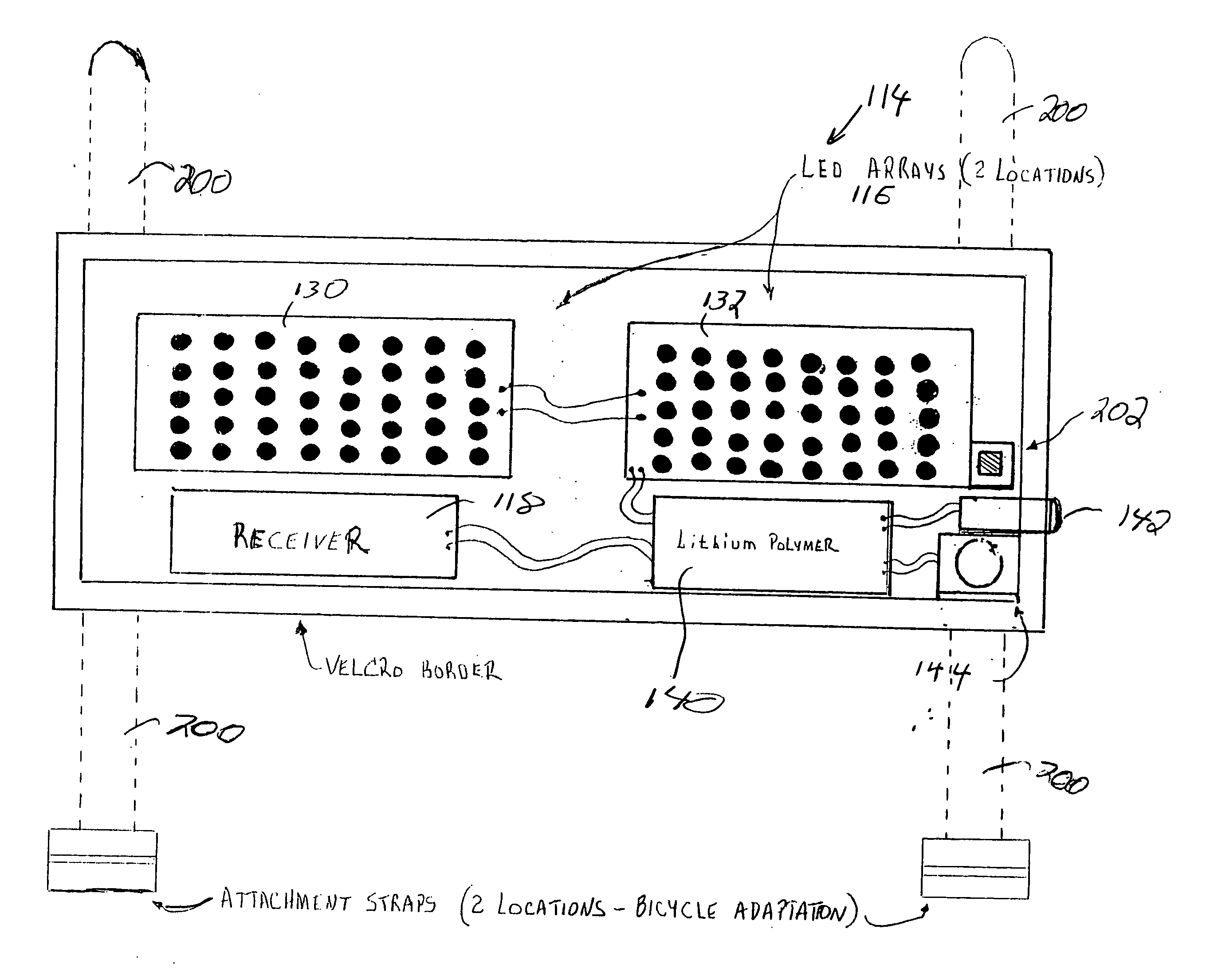
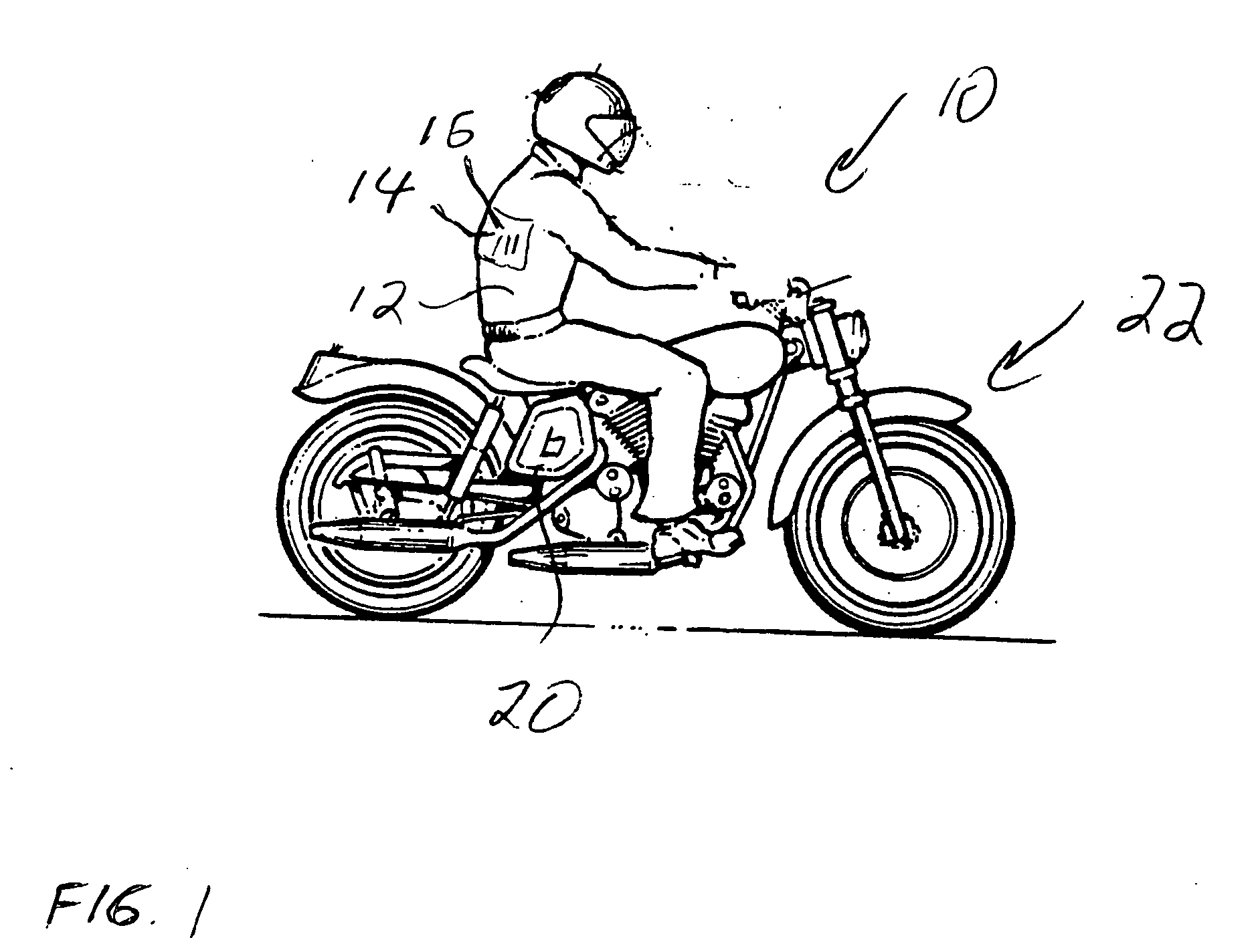
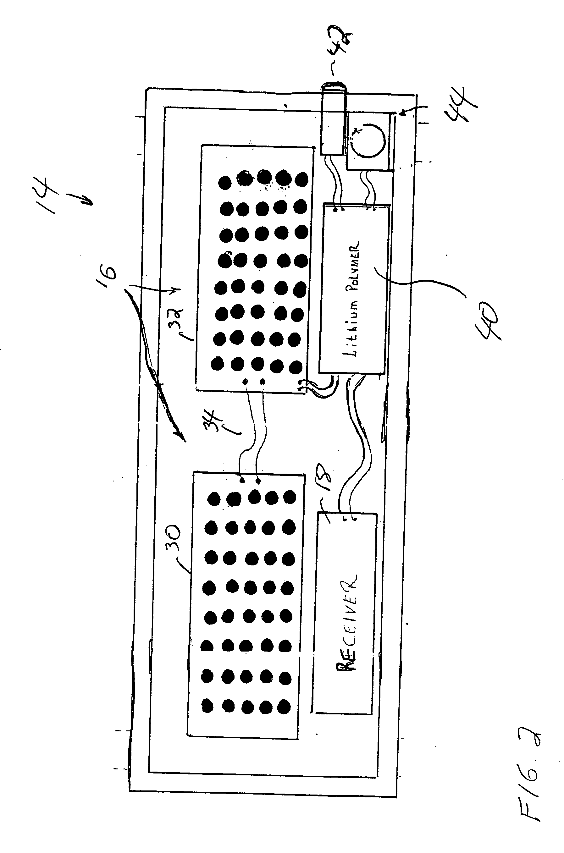
[0029] A signaling device for use by a rider on a motorcycle or bicycle is disclosed. FIG. 1 is a side view of a signaling system 10 worn by a rider 12 in the preferred embodiment of the present invention. The rider wears a jacket having an indication mechanism 14. The indication mechanism includes an LED array 16 which may provide an indication for a turn indication and brake or deceleration indications. The indication mechanism is affixed to a garment worn by the rider. The indication mechanism includes a receiver 18. The signaling system also includes a transmitter 20 affixed to a motorcycle 22. The transmitter is connected to a motorcycle signal interface 24.

[0030] Preferably, the indication mechanism is affixed to a jacket, but any garment worn by the rider may be utilized. Additionally, the indication mechanism is preferably removable and may be held in position to the garment by any attachment means, such as Velcro strips or straps. Also, in the preferred embodiment of the p...


PUM


Abstract

The present invention is a signaling system for a motorcycle or bicycle providing a light indication to other motorists. An indication mechanism is attached to a garment of the rider. The indication mechanism has at least two banks of LEDs arrays and a wireless radio receiver. A signal interface is linked to the wiring system of the motorcycle light system. The signal interface intercepts signals transmitted on the wiring system of the motorcycle light system. The system also includes a wireless radio transmitter in communication with the signal interface. When the signal interface detects a signal sent through the wiring system of the motorcycle, the signal interface sends a signal via the transmitter to the receiver of the indication mechanism. The indication mechanism then illuminates the appropriate bank of LED arrays to provide a light indication to warn other motorists. In an alternate embodiment of the present invention, the indication mechanism may be worn by a cyclist. The signal interface may communicate with a sensing device which receives signals from a braking mechanism of the bicycle. When the braking mechanism is actuated, the sensing device senses the braking action and sends a signal via the transmitter to the receiver of the indication mechanism, which in turn illuminates the LED arrays. Alternately, rather than utilizing a signal interface, the indication mechanism may include an accelerometer to detect deceleration of the bicycle.

Description

BACKGROUND OF THE INVENTION [0001] 1. Field of the Invention [0002] This invention relates to safety devices. Specifically, the present invention relates to a signaling device mounted on a garment for use with a vehicle or bicycle. [0003] 2. Description of Related Art [0004] Both motorcycles and bicycles make up a significant portion of the traffic on roads. However, although popular, there is extreme danger associated with riding motorcycles and bicycles on the road. One of the greatest problems associated with motorcycles and bicycles is the inability of many drivers to see the motorcycles / bicycles on the road. Because of their size, motorcycles / bicycles are oftentimes difficult to see. Additionally, because motorcycles have signaling lights which are smaller than conventional automobiles, drivers do not observe motorcycles signals when stopping, slowing, or indicating a turn. Likewise, drivers do not notice bicyclists providing hand signals. A device and system is needed which pr...

Claims


Application Information

Patent Timeline
Patent Type & Authority Applications(United States)
IPC IPC(8): B60Q1/44
CPCB60Q1/2673B60Q1/445B60Q2900/30B62J2006/008B62J6/04B62J27/00B62J6/005B62J6/165B62J6/045B62J6/055
Inventor PERKINS, BARRYCORDINA, JOSEPH
Owner PERKINS BARRY
Learn More