Eureka AIR delivers breakthrough ideas for toughest innovation challenges, trusted by R&D personnel around the world.

Method for converting an appliance for use with a wireless communication device

Inactive Publication Date: 2007-03-22
TECH LICENSING CORP (US)
View PDF4 Cites 3 Cited by
  • Summary
  • Abstract
  • Description
  • Claims
  • Application Information

AI Technical Summary

Benefits of technology

[0004] An appliance has a metallic housing. A radio frequency transceiver is mounted on the surface of the housing. The radio frequency transceiver is operatively coupled to an appliance control for receiving and transmitting ins

Problems solved by technology

However, these devices, although satisfactory, have suffered from the shortcomings that because of the conductive shielding nature of the metallic housing of the appliance, the antenna cannot be placed within the appliance.
However, this adds to the cost of the appliance because of the need for radio frequency connectors, the cost of external antenna and mounting hardware, the cost of the radio frequency cable to couple the circuitry and the problems associated with running the fragile cable from the appliance controller through the appliance to the antenna.

Method used


Image

  • Method for converting an appliance for use with a wireless communication device
  • Method for converting an appliance for use with a wireless communication device

Examples


Embodiment Construction

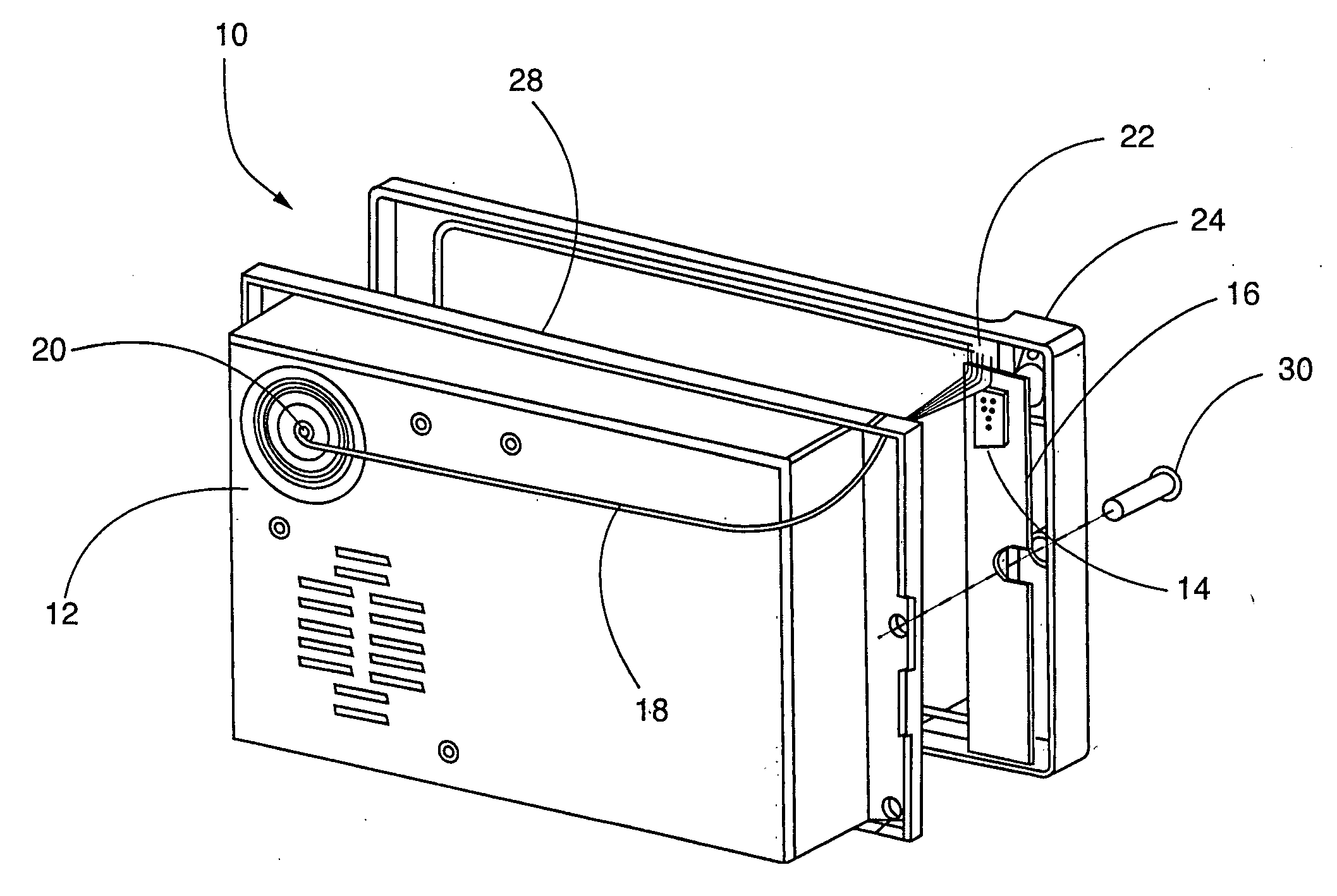
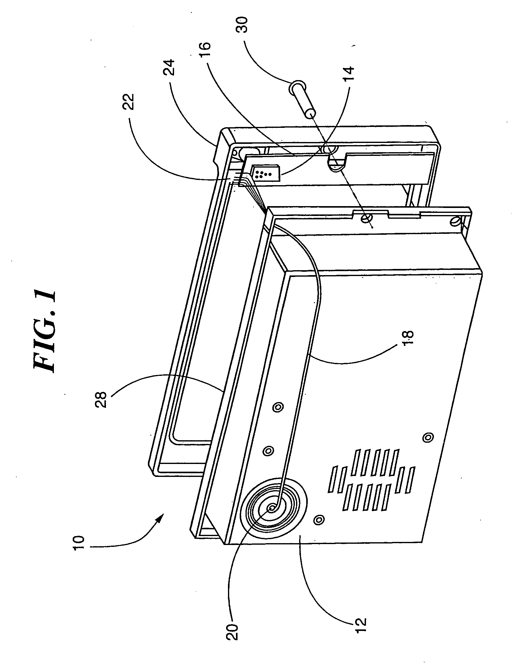
[0008] Reference is made to FIG. 1 in which an appliance, generally indicated as 10 constructed in accordance with the invention is provided. Appliance 10 includes a controller for controlling appliance 10 as known in the art. The controller is contained in a housing 12. Housing 12 is formed substantially of an electrically conductive material such as iron, stainless steel, other metals or the like, which is conductive to radio frequency signals.

[0009] Appliance 10 may be an oven, a washer, a refrigerator or the like appliance. For ease of description, appliance 10 may be referred to from time to time as an oven in an exemplary embodiment.

[0010] As is known in the art, appliance 10 is operated under the control of an onboard computer (controller), which either reports data to, or receives instructions from, a remote second control (not shown). The second control may either be a second appliance, a base station computer in wireless communication with appliance 10, a mobile device s...


PUM


Abstract

An appliance has a metallic housing. A radio frequency transceiver is mounted on the surface of the housing. The radio frequency transceiver is operatively coupled to an appliance control for receiving and transmitting instructions and information to and from the control. A bezel made of non-electrically conductive material is mounted on a surface of the housing. An antenna is operatively coupled to the transceiver and is disposed within the bezel. In one embodiment, the radio frequency transceiver is disposed between the bezel and the housing. The bezel is formed of plastic.

Description

CROSS-REFERENCE TO RELATED APPLICATIONS [0001] This. application claims priority to U.S. Provisional Application Ser. No. 60 / 719,089, entitled METHOD FOR CONVERTING AN APPLIANCE FOR USE WITH A WIRELESS COMMUNICATION DEVICE, filed Sep. 21, 2005, which is hereby expressly incorporated herein in its entirety by this reference.BACKGROUND OF THE INVENTION [0002] This invention is directed to a structure for allowing wireless communication with an appliance, and more particularly an antenna structure for allowing wireless communication with an appliance. [0003] Typically, commercial appliances such as ovens, fryers, refrigerators, washing machines or the like are constructed of stainless steel or other electrically conducting material. It is known in the art to control these devices remotely with the use of radio frequency or other electronic signals utilizing an antenna at the appliance. However, these devices, although satisfactory, have suffered from the shortcomings that because of th...

Claims


Application Information

Patent Timeline
IPC IPC(8): G08C19/00
CPCH01Q1/40G08C17/02
Inventor FLYNN, WILLIAMBREWSTER, JULIE
Owner TECH LICENSING CORP (US)
Why Eureka
Eureka Blog
Learn More