
Compensation circuit and method for reducing intersymbol interference products caused by signal transmission via dispersive media

a dispersed media and compensation circuit technology, applied in the field of signal transmission and detection, can solve the problems of nonlinear distortion of the electrical signal of the receiver, the bit rate of the data signal b>11/b>, and the length of the optical fiber b>14,/b>, and the inability to reliably receive and accurately detect transmitted data

Inactive Publication Date: 2007-03-22
MARVELL ASIA PTE LTD
View PDF16 Cites 29 Cited by
  • Summary
  • Abstract
  • Description
  • Claims
  • Application Information

AI Technical Summary

Problems solved by technology

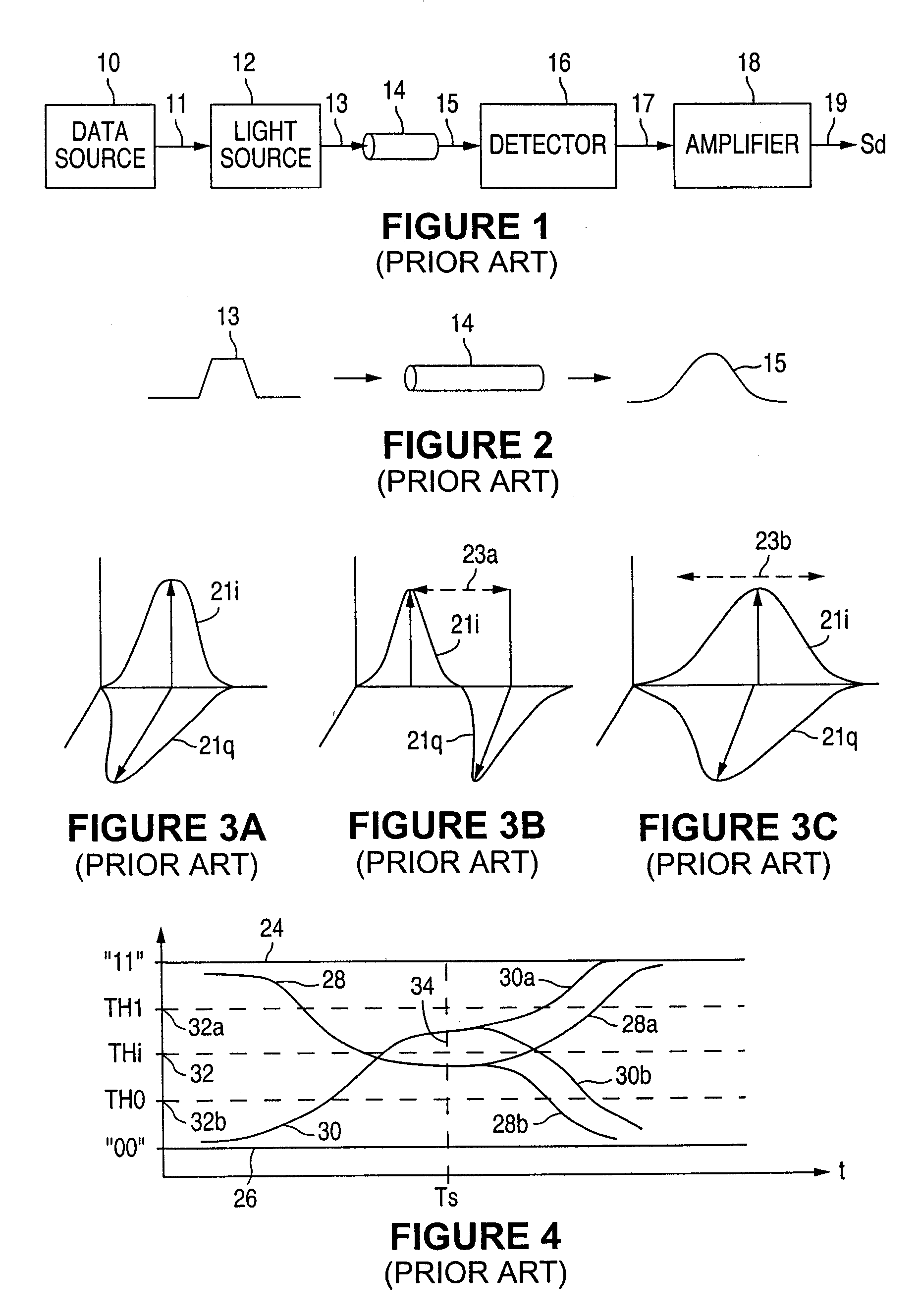
It is well known that the bit rate of the data signal 11, as well as the length of the optical fiber 14, are limited in terms of how reliably a transmitted data can be received and accurately detected, due to the non-ideal characteristics of the fiber optic transmission medium 14.
However, with direct optical signal detection, such as that done when using a photodetector, chromatic dispersion causes nonlinear distortions in the electrical signal of the receiver.
Simple conventional linear equalization techniques are not adequate for compensating for such dispersion.
With polarization dispersion occurring in addition to chromatic dispersion, simple linear equalization techniques become even less effective as well as less practical due to the increasing complexity of the equalization circuitry necessary for compensation.
However, consistent with the foregoing discussion, the dispersion effects of the optical fiber 14 are such that the value of the detected signal fails to achieve these ideal signal values due to the intersymbol interference (“ISI”) caused by the dispersion effects upon adjacent data bits as well as the present or desired data bit.
As a result, incorrect decisions may be made as to the unity or zero value of the detected signal at time Ts.
The problem with this conventional approach, is that if the distortion affects cause the opening of the signal eye to not be centered about this threshold value 32 then the signal value will be incorrectly detected.
However, while this may be effective at low data rates, it becomes significantly less effective at high data rates.
While these techniques can be somewhat effective, such techniques do nothing to remove distortion from the data signal.
Instead, such techniques merely use information about the distortion in an attempt to achieve an approximately equivalent, but inferior, effect.

Method used


Image

  • Compensation circuit and method for reducing intersymbol interference products caused by signal transmission via dispersive media
  • Compensation circuit and method for reducing intersymbol interference products caused by signal transmission via dispersive media
  • Compensation circuit and method for reducing intersymbol interference products caused by signal transmission via dispersive media

Examples


Embodiment Construction

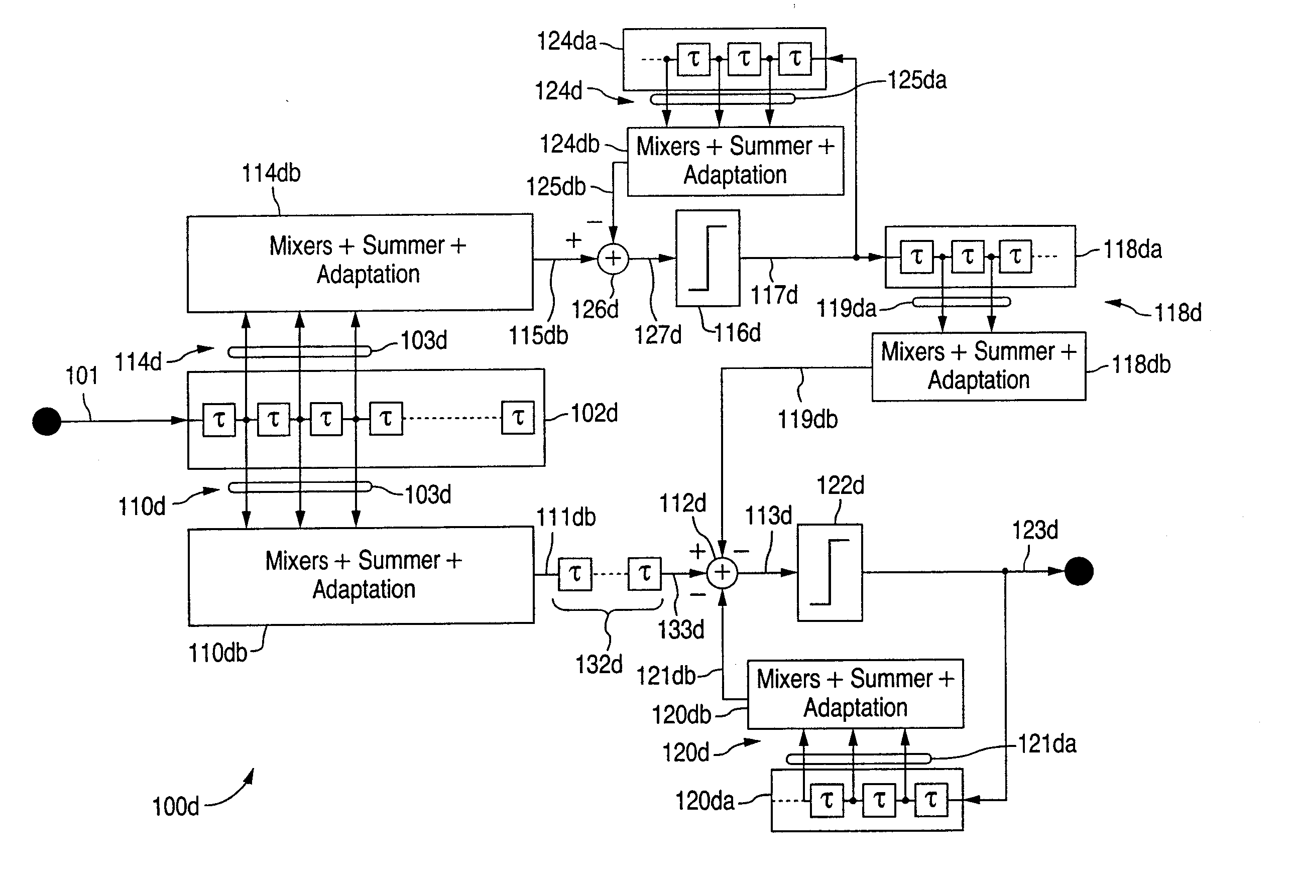
[0117] The following detailed description is of example embodiments of the presently claimed invention with references to the accompanying drawings. Such description is intended to be illustrative and not limiting with respect to the scope of the present invention. Such embodiments are described in sufficient detail to enable one of ordinary skill in the art to practice the subject invention, and it will be understood that other embodiments may be practiced with some variations without departing from the spirit or scope of the subject invention.

[0118] Throughout the present disclosure, absent a clear indication to the contrary from the context, it will be understood that individual circuit elements as described may be singular or plural in number. For example, the terms “circuit” and “circuitry” may include either a single component or a plurality of components, which are either active and / or passive and are coupled together to provide the described function. Additionally, the term...


PUM


Abstract

A compensation circuit and method for reducing ISI products within an electrical data signal corresponding to a detected data signal received via a signal transmission medium introduces distinct compensation effects for individual ISI products within the electrical data signal. Distinct data signal components within the detected data signal and corresponding to such ISI products can be selectively and individually compensated, thereby producing a compensated data signal in which each selected one of such individual data signal components is substantially removed. Individual data signal components or selected combinations of data signal components can be compensated as desired.

Description

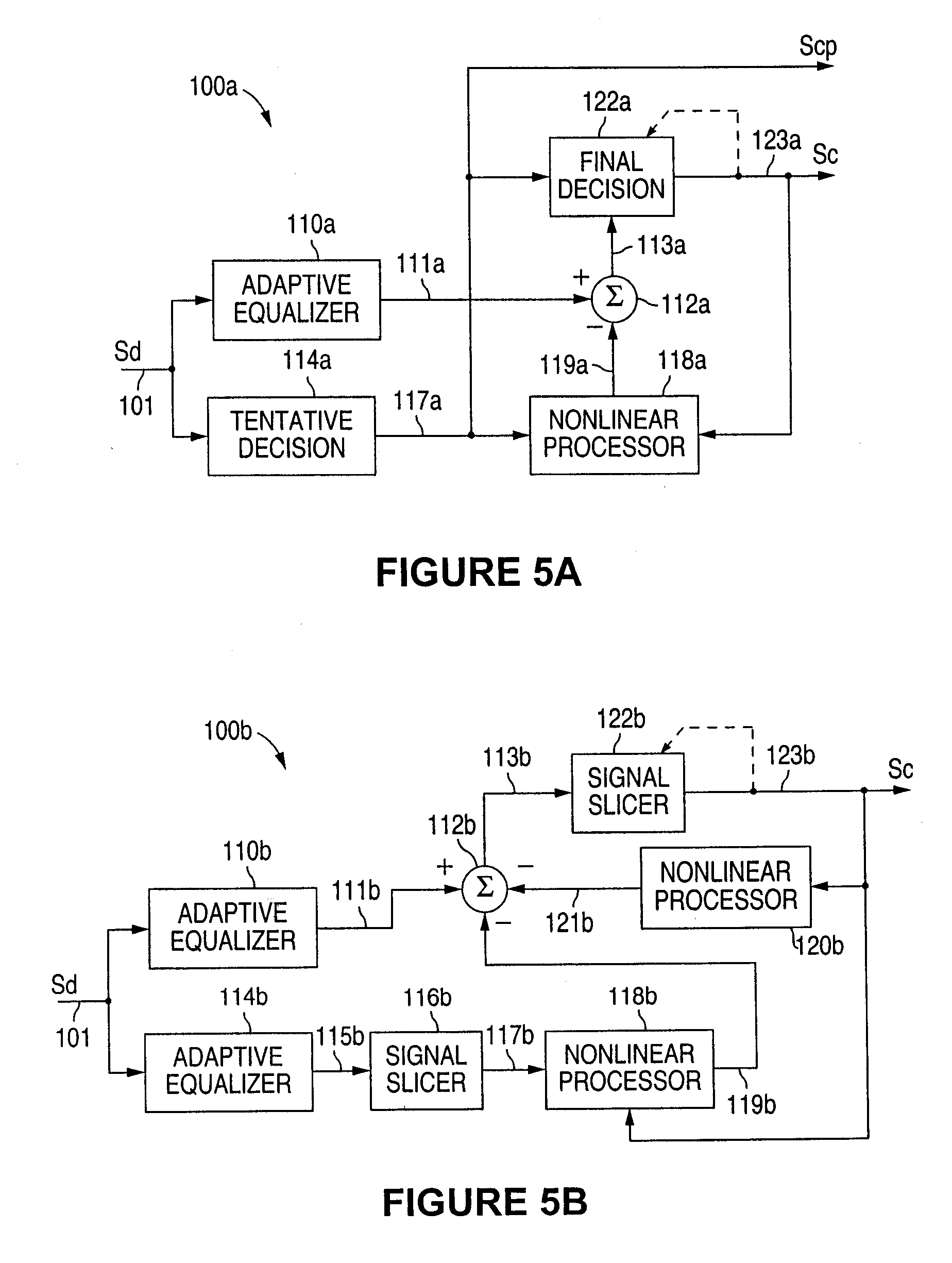
RELATED INVENTIONS [0001] This application is a continuation-in-part of U.S. application Ser. No. 10 / 117,293, filed Apr. 5, 2002.BACKGROUND OF THE INVENTION [0002] 1. Field of the Invention [0003] The present invention relates to signal transmission and detection, and in particular, to techniques for compensating for signal distortions caused by signal dispersion and nonlinearities within the signal transmission media. [0004] 2. Description of the Related Art [0005] Referring to FIG. 1, a conventional fiber optic signal system includes a data source 10, a light source (e.g., a laser) 12, the fiber optic medium 14, a signal detector (e.g., photodetector) 16 and an amplifier (e.g., transimpedance) 18, interconnected substantially as shown. The data source 10 provides a stream, or sequence, of data symbols 11 which modulate the light source 12 which, in turn, launches an optical signal 13 into the optical fiber 14. (Typically each data symbol consists of a single data bit.) At the rece...

Claims


Application Information

Patent Timeline
Patent Type & Authority Applications(United States)
IPC IPC(8): H04B1/10H03D1/06H04L1/00
CPCH04B10/6971H04L25/03038H04L25/03057H04L2025/037H04L2025/03624H04L2025/03656H04L25/03878
Inventor PHANSE, ABHIJITSHANBHAG, ABHIJIT G.
Owner MARVELL ASIA PTE LTD
Learn More