Portable band saws

a band saw and portable technology, applied in the field of portable band saws, can solve the problems of adverse effects on the operability of the band saw, and achieve the effect of minimizing or eliminating adverse effects on the weight of the battery

Active Publication Date: 2007-03-29
MAKITA CORP
View PDF7 Cites 16 Cited by
  • Summary
  • Abstract
  • Description
  • Claims
  • Application Information

AI Technical Summary

Benefits of technology

[0008] t is accordingly an object of the present invention to teach improved techniques for

Problems solved by technology

However, there has been a problem that the weight of the ba

Method used


Image

  • Portable band saws
  • Portable band saws
  • Portable band saws

Examples


Embodiment Construction

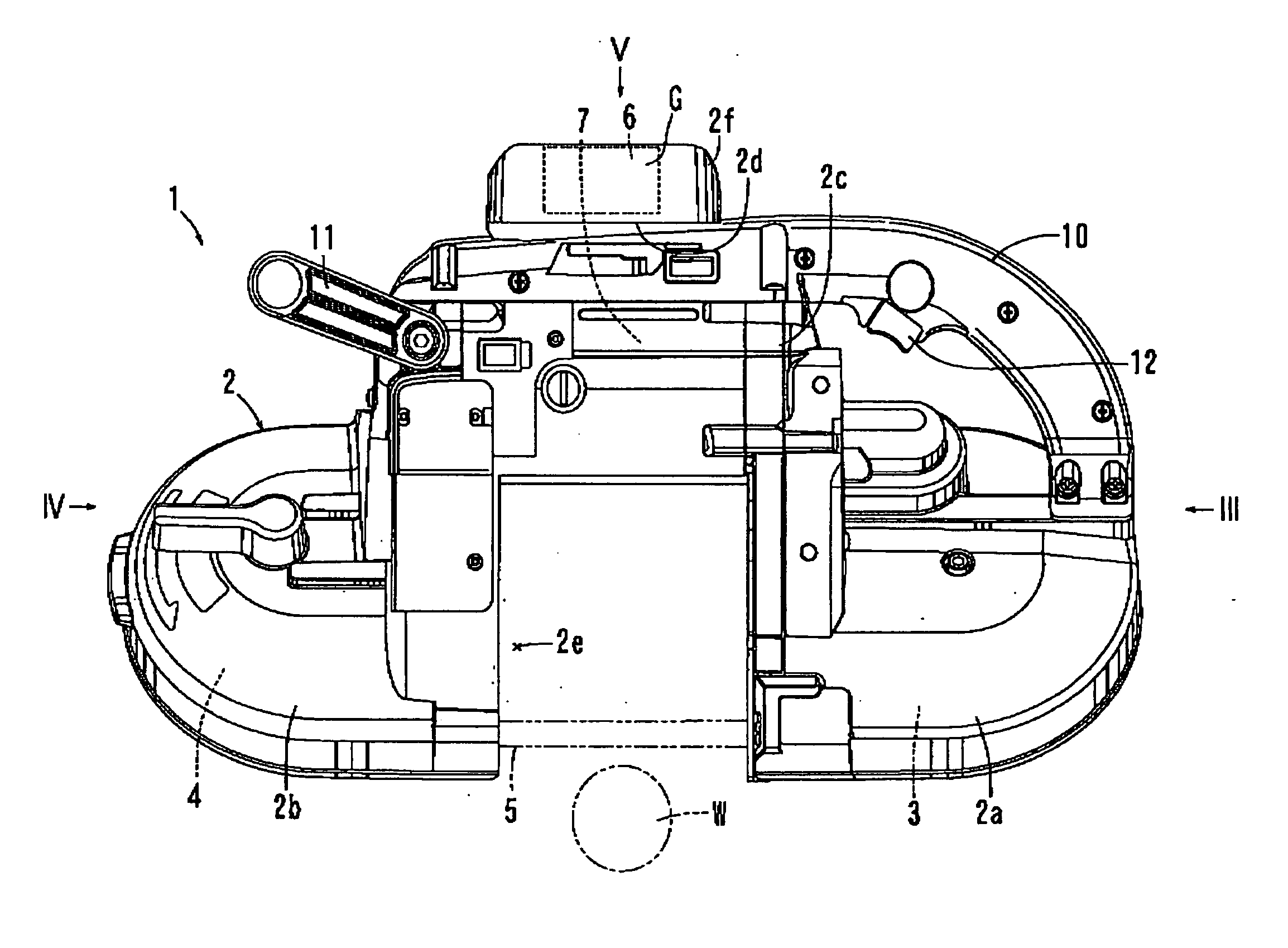
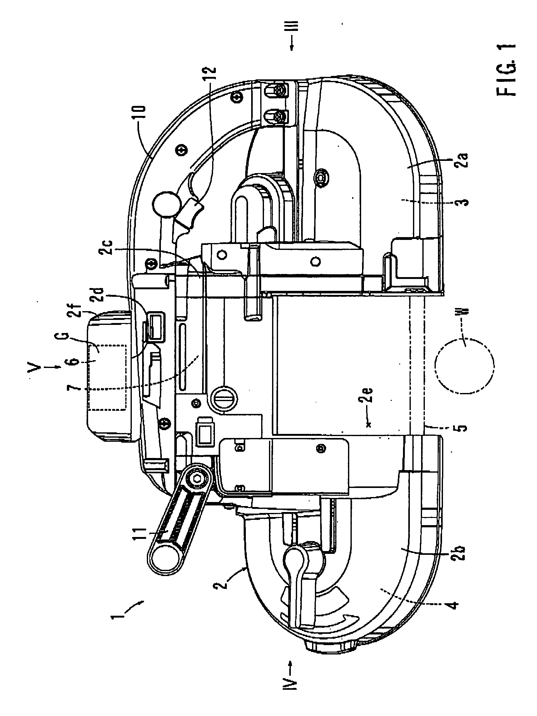
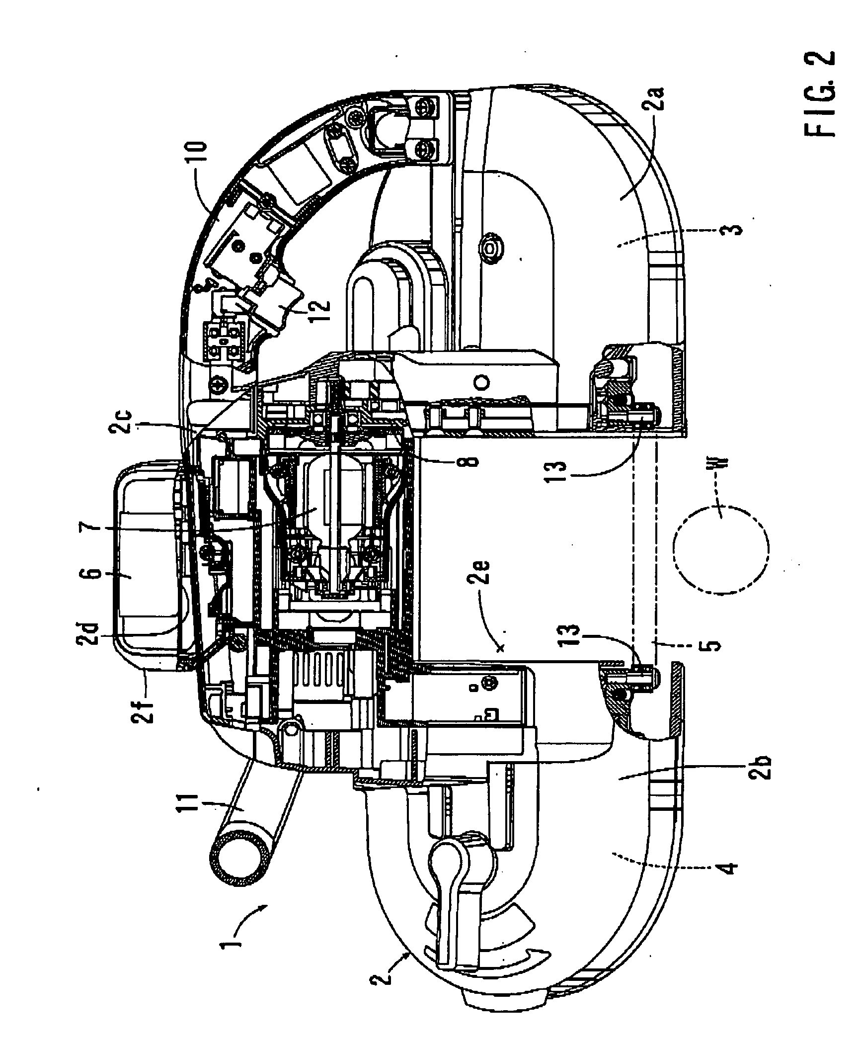
[0015] Each of the additional features and things disclosed above and below may be utilized separately or in conjunction with other feature and teachings to provide improved portable band saws. Representative examples, or the embodiments of the present invention, utilize many of these additional features and teachings both separately and in conjunction with one another, will now be described in detail with reference to the attached drawings. This detailed description is merely intended to teach a person of skill in the art further details for practicing preferred embodiments of the present invention and is not intended to limit the scope of the invention. Only the claims define the scope of the claimed invention Therefore, combinations of features and steps disclosed in the following detailed description may not be necessary to practice the invention in the broadest sense, and are instead taught merely to particularly describe representative examples of the invention. Moreover, vari...


PUM

PropertyMeasurementUnit
Lengthaaaaaaaaaa
Thicknessaaaaaaaaaa
Widthaaaaaaaaaa

Abstract

A portable band saw has a main housing and a saw band circulating within the main housing. A motor for driving the saw band is disposed within a motor housing that is mounted to the main housing. The main housing defines an opening across which the saw band moves in order to cut a workpiece. A battery for driving the motor is mounted to a motor receiving portion of the motor housing. The motor receiving portion has a width corresponding to the width of the opening and opposing to the opening in the forward and rearward directions.

Description

[0001] This application claims priority to Japanese patent application Serial number 2005-280308, the contents of which are incorporated herein by reference. BACKGROUND OF THE INVENTION [0002] 1. Field of the Invention [0003] The present invention relates to portable band saws that have a saw band driven by an electric motor. [0004] 2. Description of the Related Art [0005] Japanese Laid-Open Patent Publication No. 2001-300819 teaches a known portable band saw that may include a pair of drive wheels respectively rotatably supported on right and left end portions of a housing, a saw band extending between the drive wheels, an electric motor disposed within the upper portion of the housing in the central position with respect to right and left directions, and a light illuminating a region where the saw band intersects with a workpiece. [0006] Known portable band saws may also use an external power source or a battery as a power source in this kind of power tool. [0007] The use of the b...

Claims


Application Information

Patent Timeline
IPC IPC(8): B27B13/00
CPCB23D53/12B27B13/16B23D55/00
Inventor SHIBATA, YOSHINORIITO, AKINORI
Owner MAKITA CORP
Why Eureka
Try Eureka