Punch with self-contained punch recess adjustment indexing

a technology of indexing and punch recess, which is applied in the field of punch recess adjustment, can solve the problems that the recess adjustment cannot be made with the punch insert in situ, and is unacceptable for a canister-style punch assembly, and achieves the effect of precise recess adjustment and easy adjustmen

Active Publication Date: 2007-03-29
MATE PRECISION TOOLING
View PDF24 Cites 56 Cited by
  • Summary
  • Abstract
  • Description
  • Claims
  • Application Information

AI Technical Summary

Problems solved by technology

This, of course, is unacceptable for a canister style punch assembly since the “stock,” i.e., commercially available, punch insert and stripper bushing sets contain no recess adjustment feature.
In addition, recess adjustments cannot be made with the punch insert in situ.

Method used


Image

  • Punch with self-contained punch recess adjustment indexing
  • Punch with self-contained punch recess adjustment indexing
  • Punch with self-contained punch recess adjustment indexing

Examples


Embodiment Construction

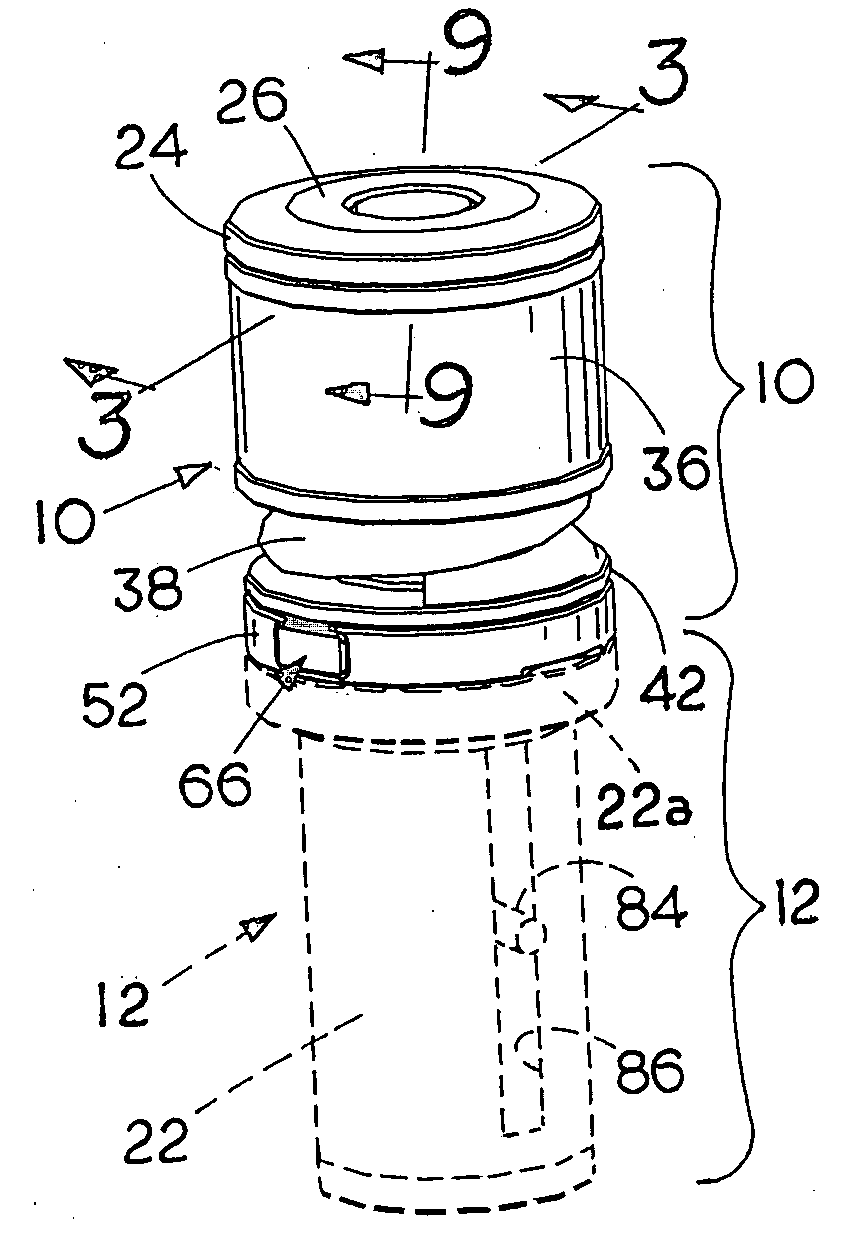
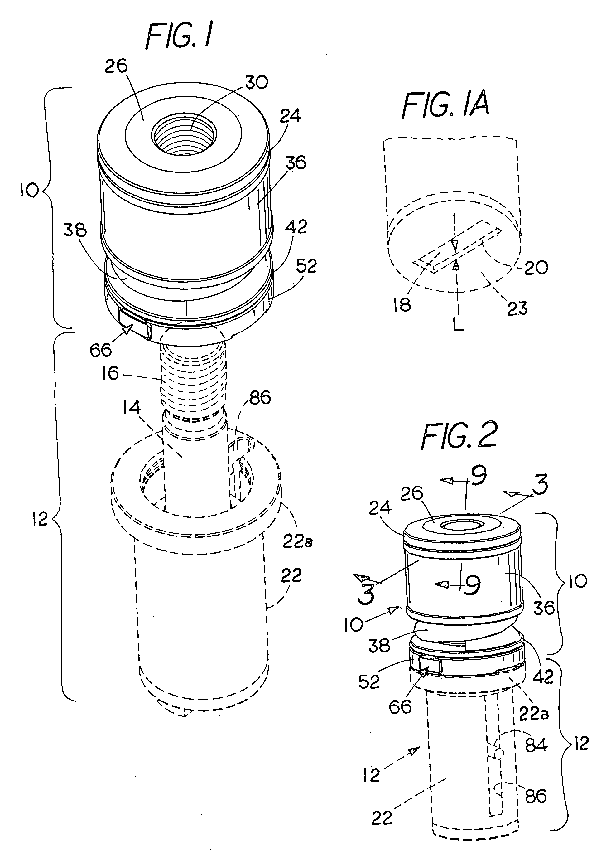
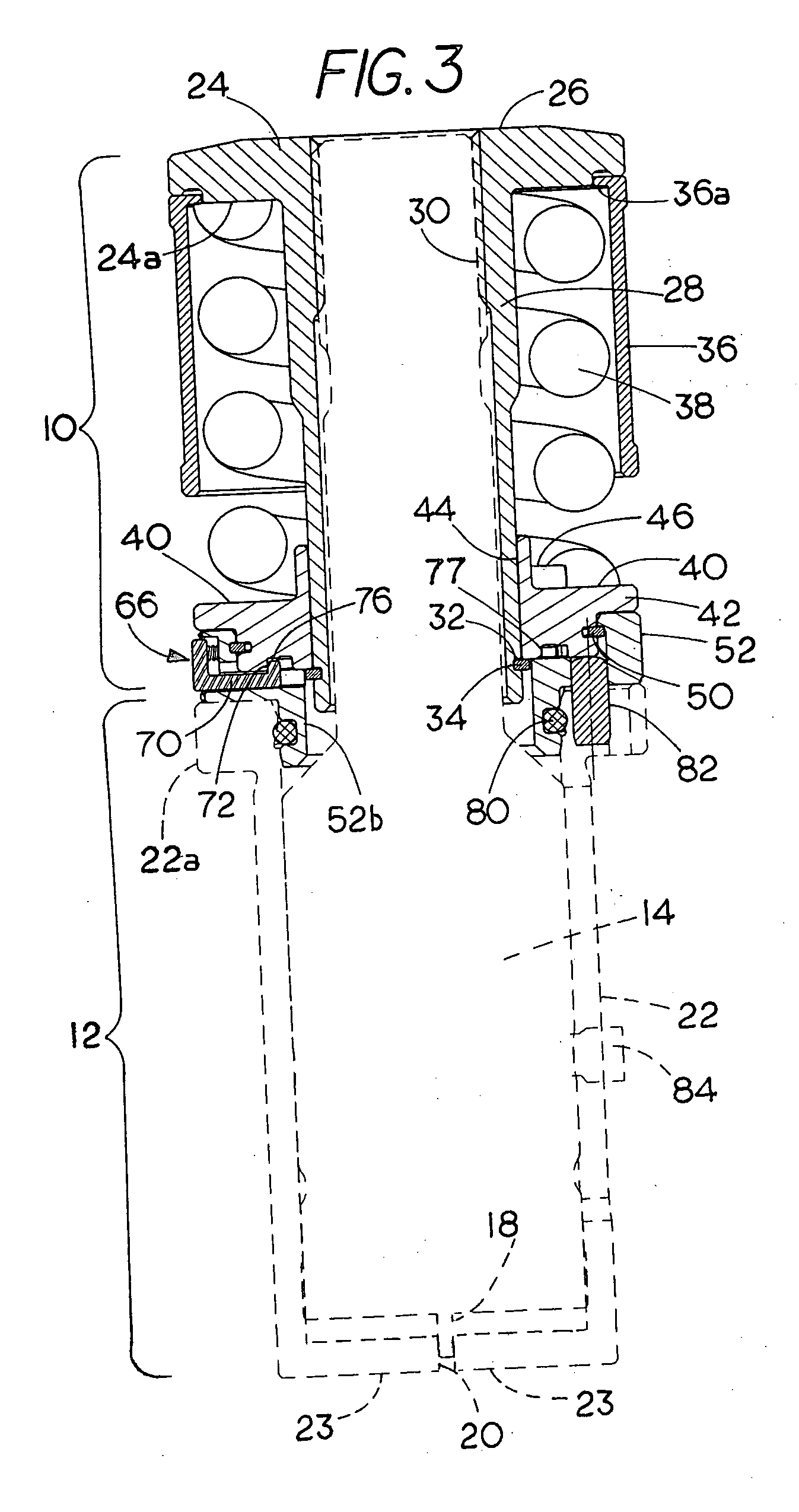
[0020] Shown in FIGS. 1, 2, and 3 is a canister 10 in accordance with the invention and a standard or “stock” punch and stripper set 12 that is available commercially from any of a number suppliers and is ordinarily provided by the end user in various standard sizes. The punch and stripper set 12 includes a punch insert 14 having a threaded upper end 16 and a punch tip 18 (FIGS. 1A and 3) that extends through a stripper opening 20 in a standard stripper guide bushing 22. At its upper end, the stripper guide bushing 22 is provided with a flange 22a that extends outwardly therefrom for supporting the punch canister 10 and punch set 12 on a punch press (not shown) during operation. The purpose of the invention is to provide, as shown in FIG. 1A, an adjustment in the recess of the tip 18 of the punch insert 14 above the lower surface 23 of the stripper bushing assembly 22. This recess distance is commonly referred to as the lead and is designated L in FIG. 1A. In many applications L is ...


PUM

PropertyMeasurementUnit
distanceaaaaaaaaaa
rotationaaaaaaaaaa
recess dimensionaaaaaaaaaa

Abstract

A punch canister includes a punch head with an axial shaft that has a screw thread which is adapted to be connected during use to the screw threads of a punch element that is slideably associated within a stripper bushing. A punch recess adjustment member is rotatably and slideably associated with the punch head. The adjustment member is adapted to the slideably but non-rotatably rotatably connected during operation to the punch element. A resilient retraction member, e.g., a spring, is located between the punch head and the adjustment member for biasing the adjustment member axially downward on the punch head. A manually releasable detent provided on the adjustment member is operatively associated with the punch head for retaining the adjustment member in any one of a plurality of selected circumferentially distributed angular positions on the punch head such that during operation disengagement of the detent allows the adjustment member and the punch element to be threaded axially on the punch head to control the distance that the punch element is recessed within the stripper bushing. In a preferred form, the detent is a lock that can be disengaged manually when the punch recess adjustment is to be made.

Description

FIELD OF THE INVENTION [0001] This invention relates to the punch and die art and especially to improved punch recess adjustment. BACKGROUND OF THE INVENTION [0002] In the punch and die art and particularly in the field of high-speed automated forming and punching equipment for punching and forming sheet material, e.g., sheet metal and especially in the case of automated turret punch presses, the punch presses are operated by computer to perform a series of punching or forming operations sequentially. These punch presses which by themselves form no part of the present invention are typically provided with an upper turret and a lower turret that rotate and are indexed intermittently between punching operations. The turrets may, for example, hold as many as a dozen or more separate punches that are used in sequence for performing given operations. When a punch is struck from above by the ram of the punch press, the punch element or punch insert is driven downwardly through the workpie...

Claims


Application Information

Patent Timeline
Patent Type & Authority Applications(United States)
IPC IPC(8): B26D7/06
CPCB21D28/34Y10T83/2159Y10T83/87Y10T83/9428Y10T83/9476
Inventor MORGAN, CHRISTOPHER D.
Owner MATE PRECISION TOOLING
Why Eureka
Try Eureka