Method and apparatus for improving cycle-life and capacity of a battery pack

Inactive Publication Date: 2007-03-29
MOTOROLA INC
View PDF6 Cites 5 Cited by
  • Summary
  • Abstract
  • Description
  • Claims
  • Application Information

AI Technical Summary

Benefits of technology

[0006] Embodiments in accordance with the invention provide a method and apparatus for improving cycle-life and capacity of a battery pack having at least a smaller capacity cell and a larger capacity cell. Although further adjusting the cutoff current of the smaller or smallest cell in the battery pack can improve the cycle life and capacity of the smaller cell and even the cycle life of the larger cell, such techniques alone will not improve the capacity of the larger cell (and of the battery pack overall). Embodiments herein enable both cells to be fully charged while maintaining each cells' optimum current cutoff point, thereby preserving cycle life performance.

Problems solved by technology

Although further adjusting the cutoff current of the smaller or smallest cell in the battery pack can improve the cycle life and capacity of the smaller cell and even the cycle life of the larger cell, such techniques alone will not improve the capacity of the larger cell (and of the battery pack overall).

Method used


Image

  • Method and apparatus for improving cycle-life and capacity of a battery pack
  • Method and apparatus for improving cycle-life and capacity of a battery pack
  • Method and apparatus for improving cycle-life and capacity of a battery pack

Examples


Embodiment Construction

[0015] While the specification concludes with claims defining the features of embodiments of the invention that are regarded as novel, it is believed that the embodiments of the invention will be better understood from a consideration of the following description in conjunction with the figures, in which like reference numerals are carried forward.

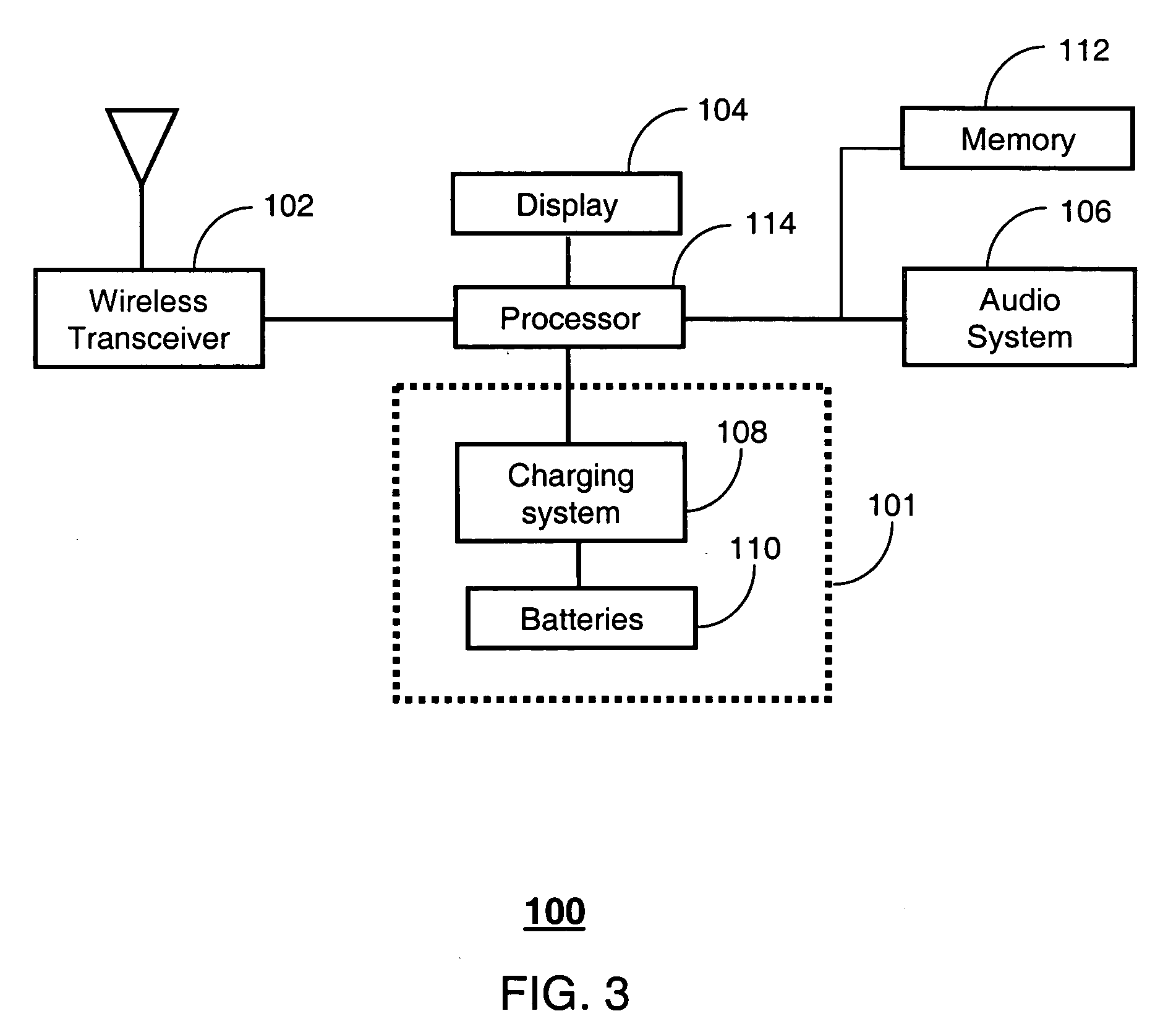
[0016]FIG. 3 is a block diagram of a device 101 in accordance with an embodiment of the present invention which can reside within a selective call receiver (SCR) 100 as will be further detailed below. The device 101 comprises a plurality of conventional battery cells 110 and a charging system 108. The charging system 108 includes, for example, a conventional regulation circuit (not shown) with conventional charge pumps if needed. The charging system 108 is coupled to the cells 110 for supplying an adjustable source voltage and source current for charging said cells 110. The battery cells 110 can be interconnected as shown in FIG. 5 and ca...


PUM


Abstract

A charging system (108) supplies a source voltage (Vco, FIG. 5) and a source current (Ico, FIG. 5) to a plurality of battery cells (110). The charging system operates according to a method (200) including the steps of determining (202) a capacity for each of the plurality of battery cells (120 and 130), determining (204) a desired cutoff current (Ico1, FIG. 5) for a select one of the plurality of battery cells (120) having the smallest capacity, determining (206) an optimal source cutoff current according to the capacity of the select one of the plurality of battery cells, adjusting (208) the source current according to the optimal source cutoff current, and periodically applying (209) the source current after reaching the optimal source cutoff current.

Description

FIELD OF THE INVENTION [0001] This invention relates generally to battery charging systems, and more particularly to a method and apparatus for improving cycle-life and capacity of a battery pack. BACKGROUND OF THE INVENTION [0002]FIG. 1 is an illustration of a prior art system for charging conventional battery cells (depicted as CELL 1 and CELL 2). In this prior art system, two cells (CELL 1 and CELL 2) are charged by way of a source current (Ico) supplied by a conventional charging system (not shown). Prior art systems generally select the source current Ico according to the cutoff current of one of the cells. The reader's attention is directed to FIG. 2, which provides a diagram depicting the relationship of cycle-life (i.e., the number of functional charge and discharge cycles of a conventional battery cell) and the charging capacity of said cell as a function of source voltage and cutoff current. From this illustration, the cutoff current of a cell is preferably 40 mA and 4.2 v...

Claims


Application Information

Patent Timeline
IPC IPC(8): H02J7/00
CPCH02J7/0075H02J7/0069
Inventor PATINO, JOSEPHSIMPSON, RUSSELL L.
Owner MOTOROLA INC
Why Eureka
Try Eureka