Cap assembly for an ink bottle

a technology of ink jet printing system and cap assembly, which is applied in the direction of packaging, printing, liquid transfer devices, etc., can solve the problems of ink spillage or leakage of excess ink/or on the operator, and ink spillage and mess within the ink jet printing system

Inactive Publication Date: 2007-04-05
VLDEOJET TECH
View PDF20 Cites 5 Cited by
  • Summary
  • Abstract
  • Description
  • Claims
  • Application Information

AI Technical Summary

Benefits of technology

[0009] The tip may also include a first protuberance inwardly-directed toward an outer surface of the shell. The first protuberance acts to assist in securing the tip to the shell and to block fluid leakage from the cap assembly. The shell may also include a second protuberance outwardly-directed toward an inner surface of the tip. The second protuberance also acts to assist in securing the tip to the shell and to block fluid leakage from the cap assembly.
[0010] Certain embodiments of the present invention also provide a method of preventing counterfeit ink bottles from being used in an ink supply system. The method includes integrally forming a first ramped feature on an exterior portion of a neck of an ink bottle, integrally forming a second ramped feature on an interior portion of a shell of a cap assembly that threadably secures to the neck of the ink bottle, allowing the first ramped feature to pass over the second ramped feature in a securing direction, and hindering the first ramped feature from passing over the second ramped feature in a direction that is opposite the securing direction. The allowing may include sliding a first ramped surface of the first ramped feature over a second ramped surface of the second ramped feature. The hindering may include abutting a first straight edge of the first ramped surface against a second straight edge of the second ramped surface.
[0011] Certain embodiments of the present invention also provide a method of preventing fluid from leaking through a cap assembly of an ink bottle when the cap assembly is closed, wherein the cap assembly includes an inner shell and an outer tip that slides between open and closed positions. The method includes providing at least one protuberance on at least one of the shell and the tip in an area between the shell and the tip, trapping excess fluid within a fluid retention area located within the cap assembly, and blocking the excess fluid from passing through the fluid retention area when the tip is closed relative to the shell with the at least one protuberance. The providing may include providing a first protuberance on an interior surface of the tip and providing a second protuberance on an exterior surface of the shell.

Problems solved by technology

When the ink bottle is replaced, excess ink may spill or leak within the ink jet printing system and / or on the operator.
Ink spills produce a mess within the ink jet printing system, and possibly outside of the system (e.g., on the surrounding flooring) and on the operator.

Method used


Image

  • Cap assembly for an ink bottle
  • Cap assembly for an ink bottle
  • Cap assembly for an ink bottle

Examples


Embodiment Construction

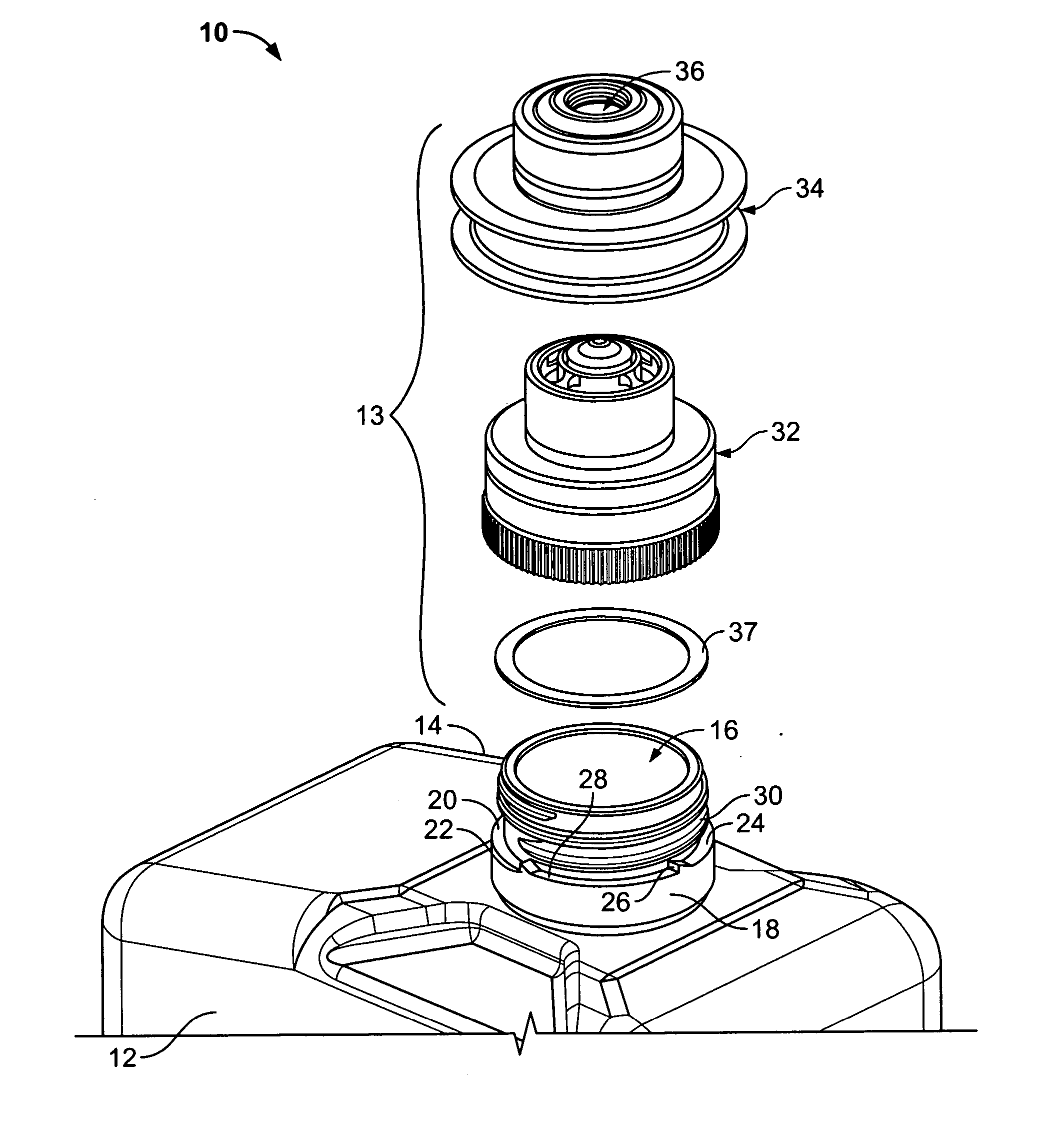
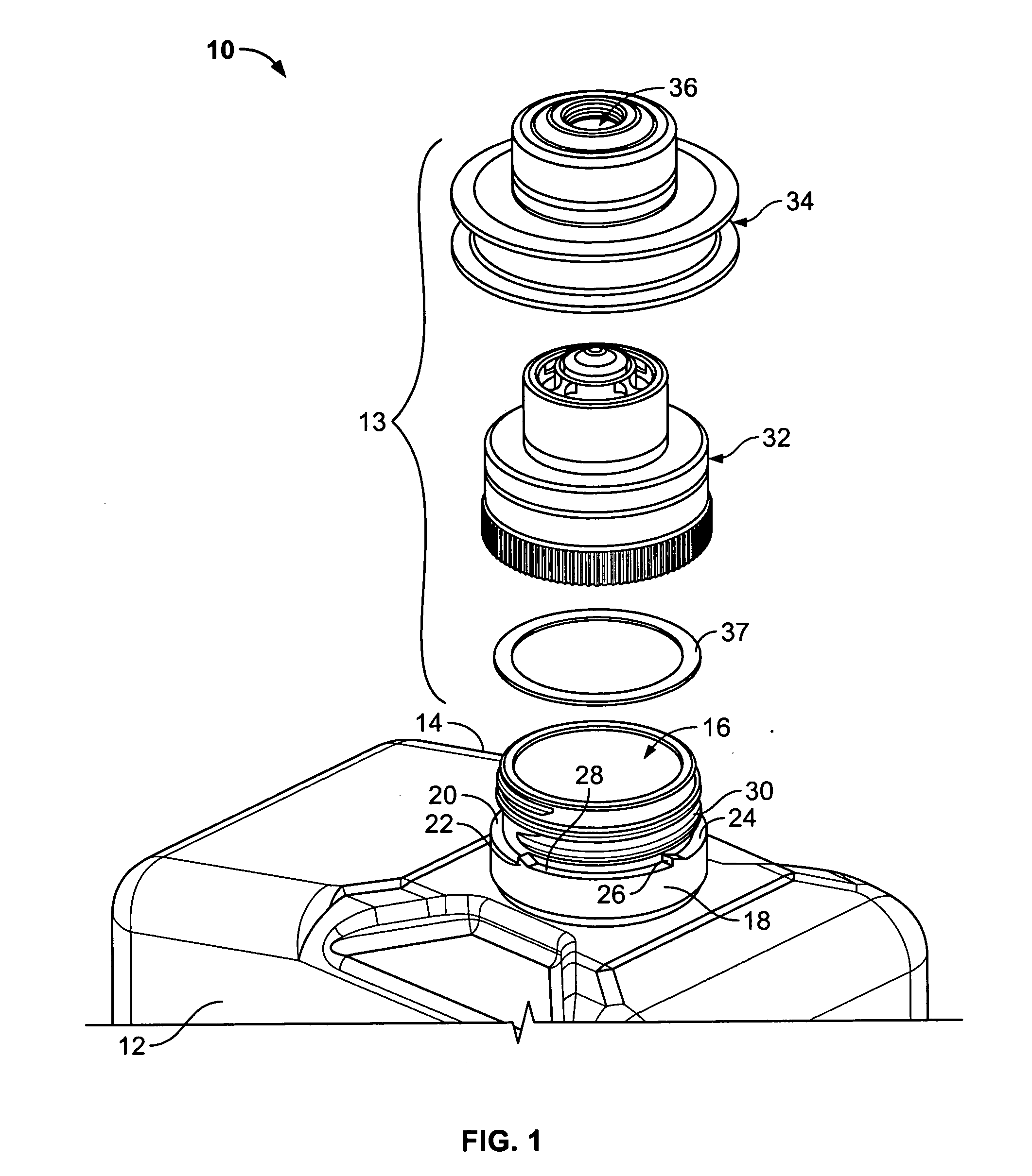
[0020]FIG. 1 illustrates an isometric exploded view of an ink bottle 10 according to an embodiment of the present invention. The ink bottle 10 may be used as part of an ink bottle connection system, such as shown and described in U.S. patent application Ser. No. 11 / 031,236, filed Jan. 6, 2005, which is hereby incorporated by reference in its entirety.

[0021] The ink bottle 10 includes a main body 12 having a fluid chamber defined therein and a cap assembly 13, which may include a keying feature(s) that allows mating with only a corresponding ink reservoir. A neck 14 extends upwardly from the main body 12 and has a fluid passage 16 defined therethrough. The fluid passage 16 allows fluid to pass from the fluid chamber into the cap assembly 13.

[0022] The neck 14 is integrally formed to the main body 12 at a base 18, which is in turn integrally formed with an upwardly extending tube 20 that defines the fluid passage 16. Upwardly extnending ratchet members, protrusion, protberances, rid...


PUM


Abstract

An ink bottle assembly for use with an ink supply system, the ink bottle assembly including a main body and a cap assembly. The main body includes a neck having at least one first ramped feature, such as a ramped ridge. The cap assembly includes a shell secured to the neck and a tip slidably secured to the shell. The shell includes a second ramped feature, wherein the second ramped feature is allowed to pass over the first ramped feature in a first direction, and wherein the second ramped feature abuts against the first ramped feature in a second direction, thereby precluding movement in the second direction.

Description

BACKGROUND OF THE INVENTION [0001] Embodiments of the present invention generally relate to ink jet printing systems, and more particularly to an improved cap assembly for an ink bottle of an ink jet printing system. [0002] Typically, ink is supplied to ink jet printing systems through the use of disposable ink bottles. An ink bottle may be mounted on an ink reservoir that includes a mating feature that allows ink to pass from the ink bottle into the ink reservoir. Each ink bottle retains a finite amount of ink, typically a pint or liter of ink. As the ink jet printing system is continually used, the ink within the ink bottle is drained. When the ink bottle is fully depleted, a new ink bottle replaces the depleted ink bottle. [0003] When the ink bottle is replaced, excess ink may spill or leak within the ink jet printing system and / or on the operator. For example, when an operator grasps the ink bottle to replace it, the force applied may squeeze the ink bottle, thereby ejecting exc...

Claims


Application Information

Patent Timeline
Patent Type & Authority Applications(United States)
IPC IPC(8): B41J2/175B67D7/34
CPCB41J2/17523B41J2/17553B65D47/243
Inventor WANG, YONGWILSON, JAMES D. IIMAYBERRY, CHARLES C.
Owner VLDEOJET TECH
Why Eureka
Try Eureka