Catheter Shaft

a catheter shaft and shaft technology, applied in the direction of catheters, etc., can solve the problems of high cost, high cost, and high cost, and achieve the effects of low roughness value, good welding ability, and good gliding properties

Inactive Publication Date: 2010-05-13
BIOTRONIK VI PATENT
View PDF5 Cites 36 Cited by
  • Summary
  • Abstract
  • Description
  • Claims
  • Application Information

AI Technical Summary

Benefits of technology

[0050]In the production of a catheter being wound from at least two film strips, each of the film strips utilized may be comprised of a different material. It is of advantage that the film strip creating the interior wall has good gliding properties due to low roughness values, and that the film strip forming the outer surface has a good ability for welding, for example, onto a balloon. As already mentioned with regard to the production method, the invention may provide that a film strip comprised of two layers is provided, which is subsequently wound into a catheter shaft. For this purpose the two layers of the film strip to be wound may also be comprised of different materials. The different materials utilized may be substantially incompatible with each other with regard to the ability for welding thereof, such as polyamide and polyimide. However, in order to still be able to realize a bonded connection by means of welding of the film strips, polyamide-typical components may be added, for example, to the polyimide.
[0051]It is generally provided that the film strip is comprised of a biocompatible polymer. At least one of the film strips utilized should be weldable to a nylon balloon. Furthermore, it is of advantage to utilize film strips having fluorine plastic or a texture in order to realize good gliding properties on the inner surface of the catheter shaft.

Problems solved by technology

Catheter shafts having a low outer diameter with a low wall thickness and the required mechanical properties can be provided only at an increased production expense and therefore at a high cost.
Although catheter shafts produced in this manner have advantageous properties, said catheter shafts are, however, dimensioned with regard to the outer diameters and wall thicknesses thereof such that the same may not be utilized for applications in very narrow vessels, such as in particular in neurovascular surgery.
Furthermore, the method of production of such catheter shafts is overall very extensive, and therefore cost-intensive.
Therefore, low wall thicknesses currently cannot be produced, because in this case the annular gap between the nozzle and the mandrel of the extrusion device would be dimensioned so narrow during the extrusion process, and thus the mass pressure would be so high that a stretching ratio of the extruder would be created, which would result in a molecule orientation in the extruder direction that would be too strong.
In this method a stretching ratio that is too high would also be present at too high of a speed.
The pronounced molecule orientation in the extruder direction has an adverse effect, particularly in extruded tubes, when the extruded tube is stressed in radial direction, such as by means of applying an increased interior pressure during the inflating of a balloon attached to the catheter shaft.
Furthermore, a molecule orientation that is too pronounced has a negative effect on welding or coating processes, also with regard to aging, since hardly any more controllable longitudinal shrinkages of the shaft may occur in these cases.
Said construction consisting of two layers mandatorily brings about a relatively large diameter such that the catheter shaft is not accessible for use particularly in narrow vessels.
The first stated embodiment of US 2005 / 0059957 A1 has the disadvantage that a relatively large diameter of the catheter shaft is produced by means of the two layers of the catheter shaft (first layer: slit tube, second layer: film), which makes the use of the catheter in very narrow vessels impossible, as mentioned above.
The second of the stated embodiments has the further disadvantage that the catheter shaft comprises no closed surface such that any fluids incorporated into the same may radially exit the shaft before they are able to fill a balloon, which is, for example, attached to the catheter shaft end.

Method used


Image

  • Catheter Shaft
  • Catheter Shaft

Examples


Embodiment Construction

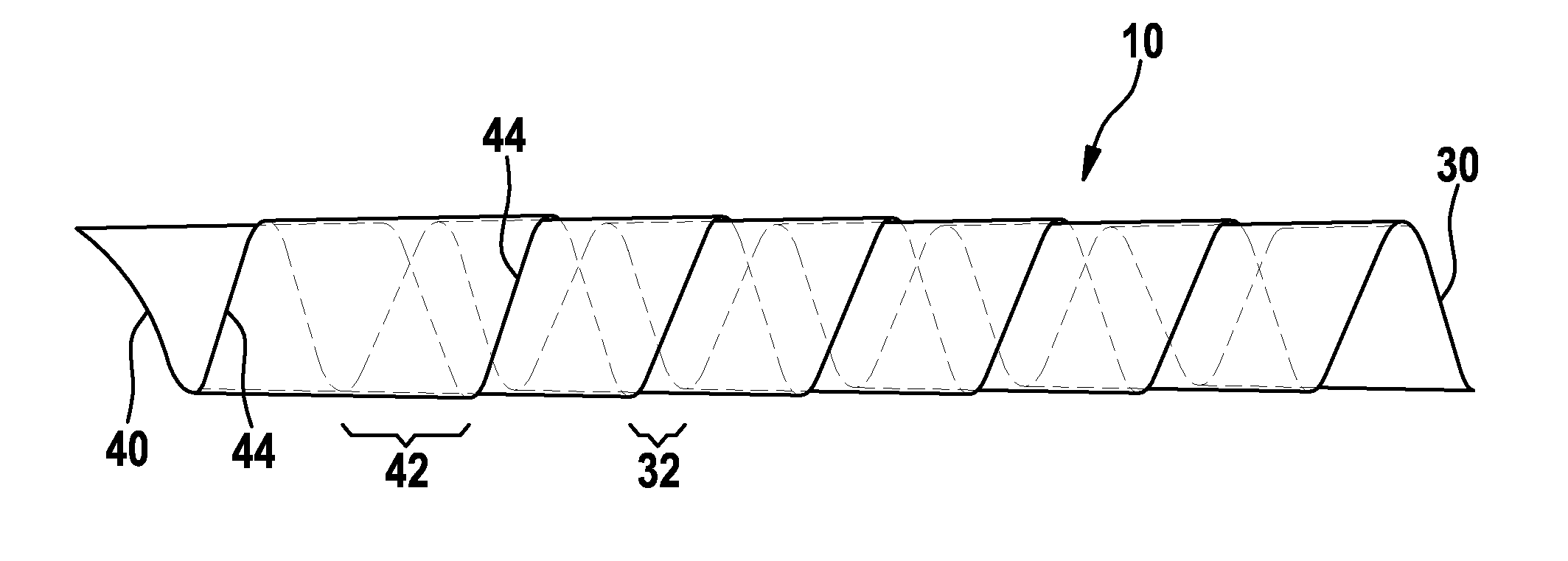
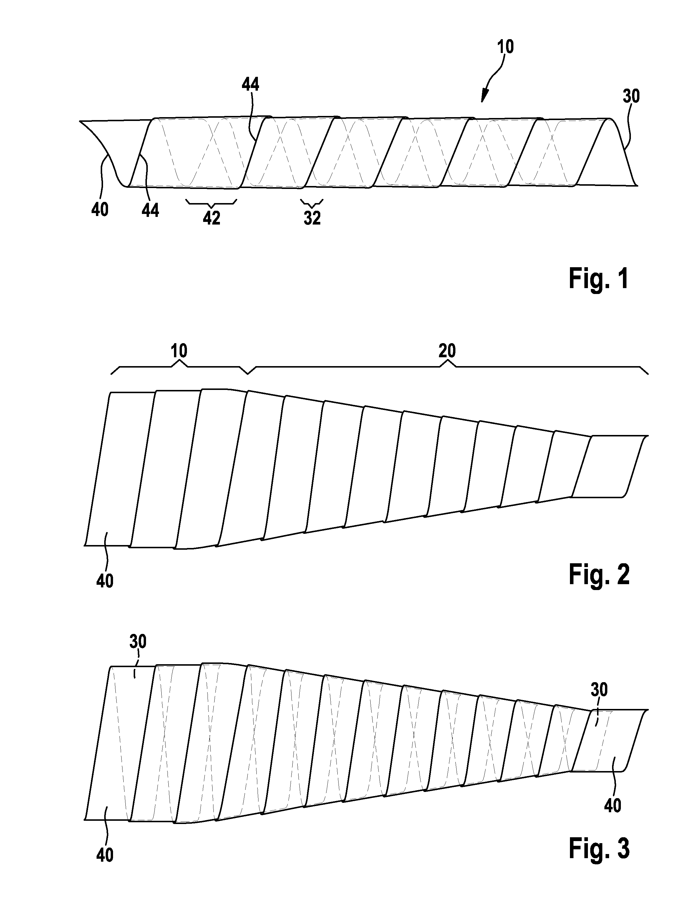
[0063]The longitudinal section of the catheter shaft illustrated in FIG. 1 is a hollow cylindrical area 10 having uncut ends. This means that the ends of the longitudinal section illustrated in FIG. 1 should be cut for an easier connection of a balloon or a grip by means of welding or gluing. The longitudinal section illustrated in FIG. 1 is wound from two film strips 30 and 40, wherein the second film strip 40 is wound over the windings of the first film strip 30. It can be seen that both film strips 30 and 40 have opposite inclines. This means that the first film strip 30 has a clockwise incline, and the second film strip 40 has a counter-clockwise incline. This results in the two film strips 30 and 40 overlapping each other in a crosswise manner. Such crosswise overlapping has the advantage of a uniform distribution of the overlapping regions across the lateral surface of the longitudinal section, or of the catheter shaft. Therefore, uniform torsion stiffness is ensured upon init...


PUM

PropertyMeasurementUnit
thicknessaaaaaaaaaa
thicknessesaaaaaaaaaa
thicknessaaaaaaaaaa

Abstract

The invention relates to a method for the production of at least one longitudinal section of a catheter, wherein the method comprises the winding of film, and the film is provided in the form of strips, the film strip is wound in the manner of a screw such that the side edges of the film strip extending in the manner of a thread overlap the film strip, and further a bonded connection is created in the overlapping region such that the longitudinal section has a closed and at least fluid-tight surface. The invention further relates to a catheter produced according to the method, and a device for carrying out the method.

Description

CROSS REFERENCE TO RELATED APPLICATIONS[0001]This invention claims benefit of priority to Germany patent application serial number DE 10 2008 043 541.4, filed on Nov. 7, 2008; the contents of which are herein incorporated by reference in their entirety.FIELD OF THE INVENTION[0002]The present invention relates to a method for the production of a longitudinal section of a catheter, the catheter including said longitudinal section, and a device for carrying out the method of production.BACKGROUND OF THE INVENTION[0003]The catheter according to the invention is suitable for probing and for draining or filling human or animal hollow organs, and for the inflation or deflation of a balloon attached to a catheter, such as in vascular intervention, particularly in PTCA or neurovascular applications.[0004]Such catheters, having a long shaft section including a hollow interior cross-section, must be able to withstand high loads of tension, pressure and torsion with an elastic behavior. Further...

Claims


Application Information

Patent Timeline
Patent Type & Authority Applications(United States)
IPC IPC(8): A61M25/00B29C53/58
CPCA61M25/0009A61M25/005A61M25/0043
Inventor GIELENZ, GERHARDHOFMANN, EUGEN
Owner BIOTRONIK VI PATENT
Why Eureka
Try Eureka