Pressure Sensitive Bypass Defrost System

a bypass defrost and pressure-sensitive technology, which is applied in the field of defrost arrangement of air exchange ventilators, can solve the problems of increasing pressure drop and building up, and achieve the effects of limiting the depressurization effect, increasing pressure drop, and maintaining the heating capacity of the heat exchanger

Inactive Publication Date: 2007-04-19
IMPERIAL SHEET METAL
View PDF7 Cites 23 Cited by
  • Summary
  • Abstract
  • Description
  • Claims
  • Application Information

AI Technical Summary

Benefits of technology

[0017] The advantage of the present invention is that it provides an improved heat recovery ventilator defrost system utilizing a bypass section which supplies warm air in both channels of the heat exchanger to accelerate defrost, continue some ventilation of stale cold air, and recirculate a portion of the warm stale air flow to limit the depressurization effect, so as to maintain the heating capacity of the heat exchanger.
[0018] Yet another advantage of the present invention is that it provides an improved heat recovery ventilator defrost system which utilizes a non-motorized bypass section for supplying warm air to both channels of the heat exchanger.
[0019] A still further advantage of the present invention is that it provides an improved heat recovery ventilator defrost system which uses two independent air flows for defrosting of the heat exchanger.
[0020] A still further advantage of the present invention is that it provides a means for protection against system failures. A malfunction that would have both motors operate continuously in wintertime would eventually produce frost build up in the stale air passageway of the heat recovery element, thus increasing the pressure drop that would in turn open the bypass section to let the warm stale air flow in the fresh air passageway to reheat the heat exchanger.
[0021]FIG. 1 is a side perspective view, which illustrates the intake of fresh air and exhaust of stale air in a conventional air exchange ventilation system;
[0022]FIG. 2 is a side perspective view of one embodiment of the present invention, which illustrates the intake of fresh air and exhaust of stale air, and which illustrates the airflow of two independent air flows for defrosting of the heat exchanger; and

Problems solved by technology

A malfunction that would have both motors operate continuously in wintertime would eventually produce frost build up in the stale air passageway of the heat recovery element, thus increasing the pressure drop that would in turn open the bypass section to let the warm stale air flow in the fresh air passageway to reheat the heat exchanger.

Method used


Image

  • Pressure Sensitive Bypass Defrost System
  • Pressure Sensitive Bypass Defrost System
  • Pressure Sensitive Bypass Defrost System

Examples


Embodiment Construction

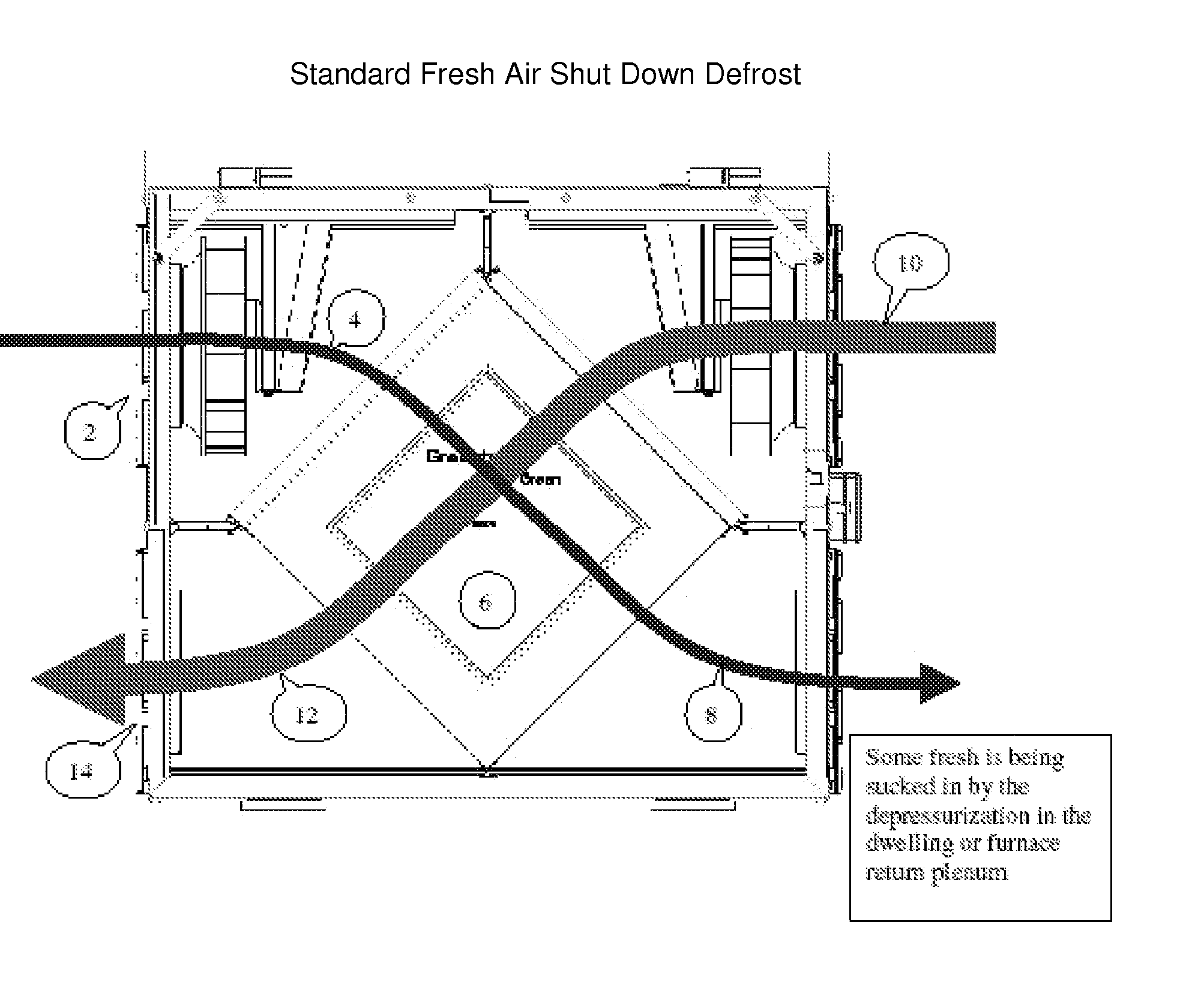
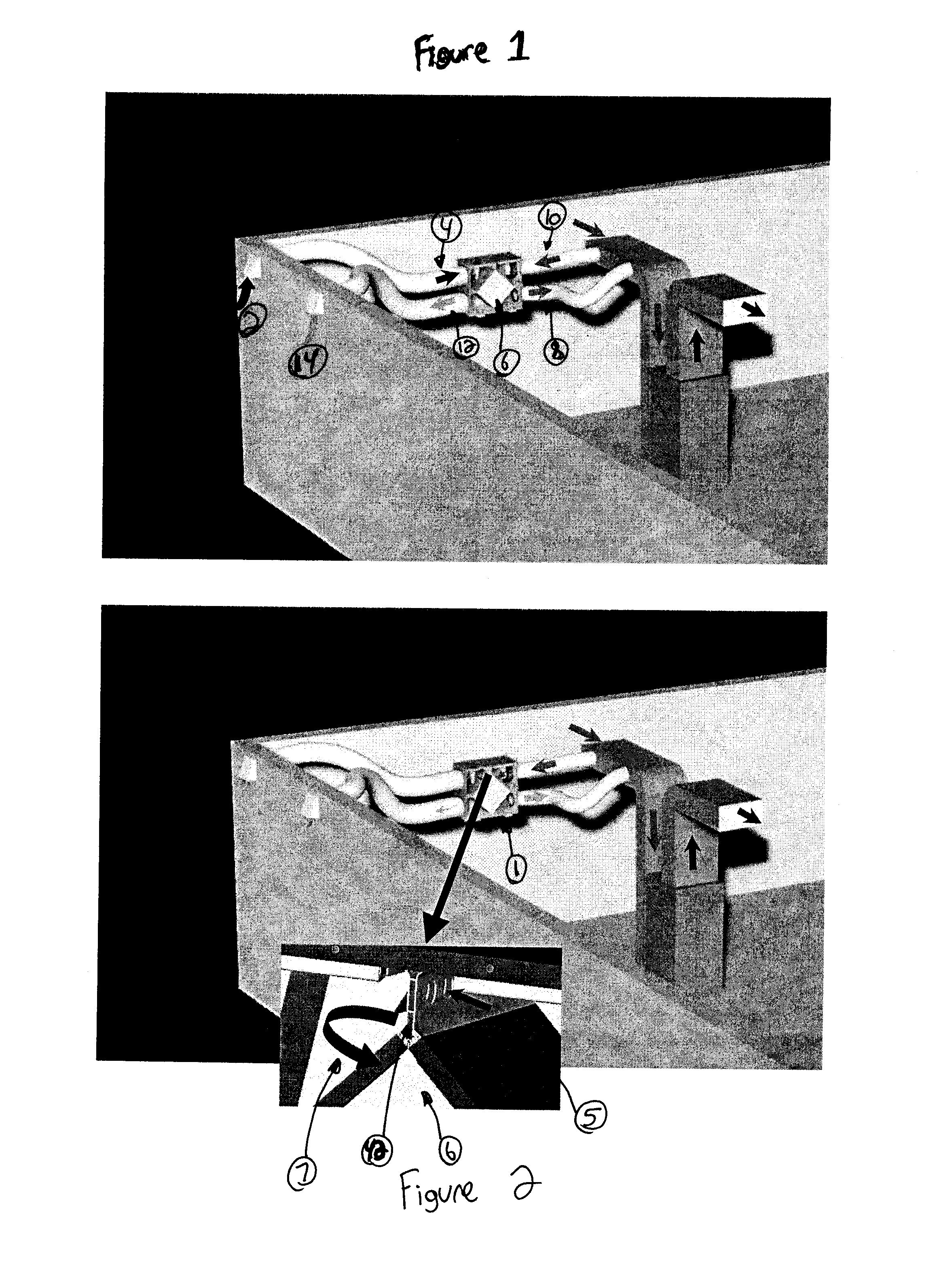
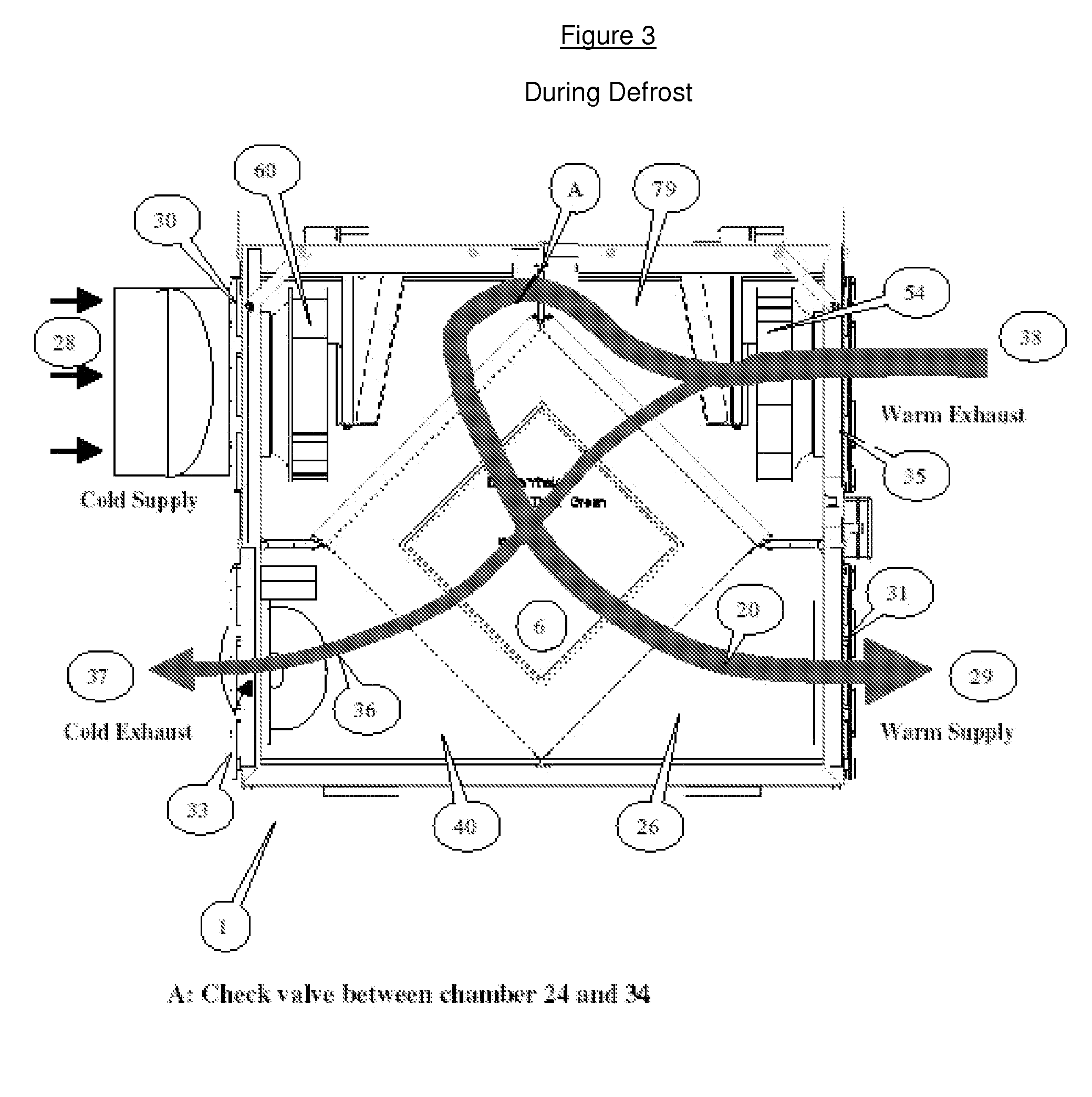
[0028] The present invention provides a defrost arrangement for air exchange ventilators which includes a heat exchanger to extract heat from the stale air and transfer it to the incoming fresh air, and which introduces warm air in both channels of the heat exchanger to accelerate defrost, continue some ventilation of stale warm air, and recirculate a portion of the stale air flow at mild temperatures as opposed to the lower temperatures of incoming fresh air. In conventional systems, during the defrost mode the fresh air motor shuts off, and warm stale air is used to defrost the heat exchanger. This air is then totally expelled outdoors which can contributes to the depressurization within the dwelling or building. With reference to FIGS. 1 and 4, incoming fresh air is admitted into the air exchange system at (2) to flow through an inlet passageway (4), which is then passed through the heat exchanger (6), to flow (8) into an enclosure. Exhaust air to be discharged from the enclosure...


PUM


Abstract

A heat recovery ventilator defrost system utilizing a bypass section which supplies warm air in both channels of the heat exchanger to accelerate defrost, continue some ventilation of stale warm air, and recirculate a portion of the stale air flow, so as to warm incoming cold fresh air. When the system is in defrost mode, warm exhaust air to be expelled enters an exhaust inlet port and into an exhaust plenum. Because the air being exhausted (by way of the exhaust fan) through the exhaust plenum is under a positive pressure, the stale air will still be sucked out through exhaust passageway into discharge plenum, but also through the passive non-motorized bypass section into inlet plenum. Further, because fresh air continues to be drawn into inlet plenum, due to the positive pressure, the warm stale air which has passed through the bypass section (flap) into inlet plenum is then drawn through the heat exchanger along the inlet passageway into supply plenum, and out through supply port into the enclosure or dwelling. In this way, the heat recovery ventilators defrost system of the present invention supplies warm air in both channels of the heat exchanger.

Description

BACKGROUND OF THE INVENTION [0001] 1. Field of the Invention [0002] This invention relates to air exchange ventilators for admitting fresh air into an enclosure while exhausting stale air. More particularly, this invention relates to a defrost arrangement for air exchange ventilators which include a heat exchanger to extract heat from the stale air and transfer it to the incoming fresh air, and which introduces warm air in both channels of the heat exchanger to accelerate defrost, continue some ventilation of stale warm air, and recirculate a portion of the stale air flow at mild temperatures as opposed to the lower temperatures of incoming fresh air. [0003] 2. Description of the Related Art [0004] Highly energy efficient buildings are generally designed to avoid uncontrolled intake and out-take of air. As some air exchange is necessary to remove stale air and replace it with fresh air, it is desirable in winter to first remove heat and or energy from the stale air and replace it wi...

Claims


Application Information

Patent Timeline
Patent Type & Authority Applications(United States)
IPC IPC(8): F28F27/02
CPCF24F12/006Y02B30/563F24F2012/007F24F2011/0087F24F11/41Y02B30/56
Inventor POIRIER, BERTRAND
Owner IMPERIAL SHEET METAL
Why Eureka
Try Eureka