Image display device and optical element for forming stereoscopic image used in the same

a technology of image display device and optical element, which is applied in the direction of optics, instruments, electrical devices, etc., can solve the problems that the addressability or modulation transfer function (mtf) in the horizontal axis will never increase to improve image quality, and achieve the effect of improving image quality

Inactive Publication Date: 2007-04-19
WINTEK CORP
View PDF7 Cites 50 Cited by
  • Summary
  • Abstract
  • Description
  • Claims
  • Application Information

AI Technical Summary

Benefits of technology

[0010] An object of the invention is to provide an image display device that has an improved image quality and is capable of being switched between 2D and 3D display modes.
[0011] Another object of the invention is to provide an optical element for forming stereoscopic images that allows the implementation of sub-pixel rendering (SPR) in conjunction with a horizontally double-density pixels (HDDP) structure to improve image quality.
[0013] Through the design of the invention, since the view-separation elements in one row are staggered relative to the view-separation elements in immediately adjacent rows, each eye of an observer can see either of two complementary delta RGB sub-pixel arrangements. Under the circumstance, both red and green sub-pixels are available in each vertical column and horizontal row in a delta RGB sub-pixel arrangement to provide full color capability, and the sub-pixel rendering technique thus can be performed in conjunction with the delta RGB sub-pixel arrangement to improve image quality.

Problems solved by technology

As a result, even if the sub-pixel rendering technique performs in conjunction with the strip pixel arrangement, either addressability or modulation transfer function (MTF) in the horizontal axis will never increase to improve image quality.

Method used


Image

  • Image display device and optical element for forming stereoscopic image used in the same
  • Image display device and optical element for forming stereoscopic image used in the same
  • Image display device and optical element for forming stereoscopic image used in the same

Examples


Embodiment Construction

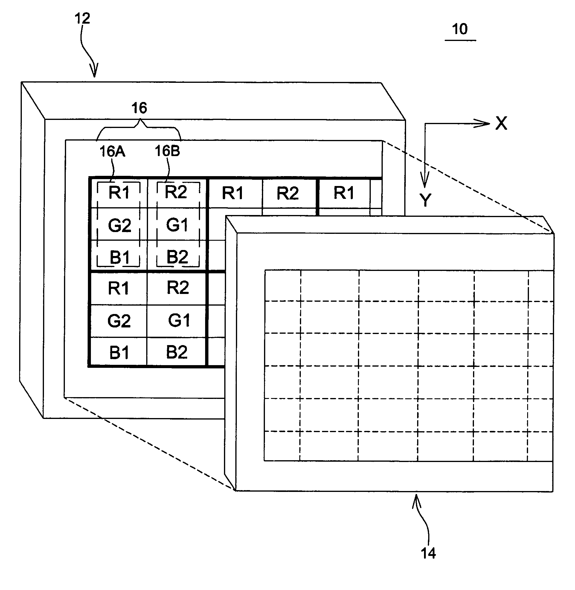
[0025]FIGS. 4A and 4B show schematic diagrams illustrating an embodiment of the invention. In this embodiment, an image display device 10 includes a display panel 12 and a liquid crystal shutter 14 placed at one side of the display panel 12. The display panel 12 may be a LCD panel having a pixel arrangement similar to the horizontally double-density pixel (HDDP) structure. Specifically, referring to FIG. 4A, a horizontal RGB stripe arrangement is chosen where RGB sub-pixels arranged in the horizontal direction (X-direction) have identical colors, and RGB sub-pixels arranged in the vertical direction (Y-direction) have distinct colors. Besides, the screen area is partitioned into multiple pixel blocks 16, and each pixel block 16 is divided into a rectangular pixel 16A (including R1, G2, and B1 sub-pixels) and a rectangular pixel 16B (including R2, G1, and B2 sub-pixels) for respectively representing left-eye and right-eye image data. In this embodiment, the respective pixels for the ...


PUM


Abstract

An image display device includes a display panel and a parallax optic. The display panel is provided with a stripe sub-pixel arrangement in which sub-pixels arranged in a first direction have identical colors, and sub-pixels arranged in a second direction have distinct colors. The pixel density in the first direction is twice the pixel density in the second direction of the stripe sub-pixel arrangement. The parallax optic has view-separation elements arranged in the first direction into multiple rows. Each view-separation element is positioned corresponding to two adjacent sub-pixels, and the view-separation elements in one row are staggered relative to the view-separation elements in immediately adjacent rows.

Description

BACKGROUND OF THE INVENTION [0001] (a) Field of the Invention [0002] The invention relates to an image display device, and particularly to an image display device capable of being switched between 2D and 3D display modes. [0003] (b) Description of the Related Art [0004]FIG. 1 shows a schematic diagram illustrating a conventional image display device 100 in which a parallax optic is installed to create stereoscopic images. Referring to FIG. 1, the image display device 100 includes a liquid crystal panel 102 and a parallax barrier plate 104. The parallax barrier plate 104 consisting of a glass substrate 118 and multiple spaced opaque stripes 120 formed thereon is in contact with one side of the liquid crystal panel 102. The barrier plate 104 is used as a view-separation optic to block one eye from seeing any images prepared for the other eye. [0005] In the liquid crystal panel 102, a liquid crystal layer 110 is sandwiched between a pair of glass substrates 106 and 108. Further, a pola...

Claims


Application Information

Patent Timeline
Patent Type & Authority Applications(United States)
IPC IPC(8): G02B27/22G02B30/31
CPCG02B27/225H04N13/0404H04N13/0409H04N13/0415H04N13/0422H04N13/0452H04N13/305H04N13/324H04N13/356H04N13/31H04N13/317G02B30/31
Inventor WANG, WEN-CHUNLIN, HAN-CHANGWU, FA-CHENWANG, YI-CHIN
Owner WINTEK CORP
Why Eureka
Try Eureka