Machining apparatus

a technology of machining apparatus and machine tool, which is applied in the direction of electric programme control, instruments, program control, etc., can solve the problems of inefficient cutting process of hundreds of thousands of dimples on a light guide plate one by one, inconvenient operation, and easy breakage of ball end mills, so as to achieve rapid and precise micromachining

Inactive Publication Date: 2007-04-19
FANUC LTD
View PDF10 Cites 4 Cited by
  • Summary
  • Abstract
  • Description
  • Claims
  • Application Information

AI Technical Summary

Benefits of technology

[0016] Being structured as above, the present invention enables rapid and precise micromachining at an exact pitch with only a light and dark pattern.

Problems solved by technology

Machining hundreds of thousands of dimples on a light guide plate one by one by a cutting process is inefficient because it takes too much time.
A problem in high speed machining with a small-diameter ball end mill is that the ball end mill is easily broken.
Ordinary machine tools are limited, however, to machining at most a few dimples per second due to the limited speed of the numerical controller or the limited response speed of the machine tool.
When a laser machine is used, the machining speed becomes higher, but this machining method uses a melting process, so the machining profile is less precise than in a cutting process.

Method used


Image

  • Machining apparatus
  • Machining apparatus
  • Machining apparatus

Examples


Embodiment Construction

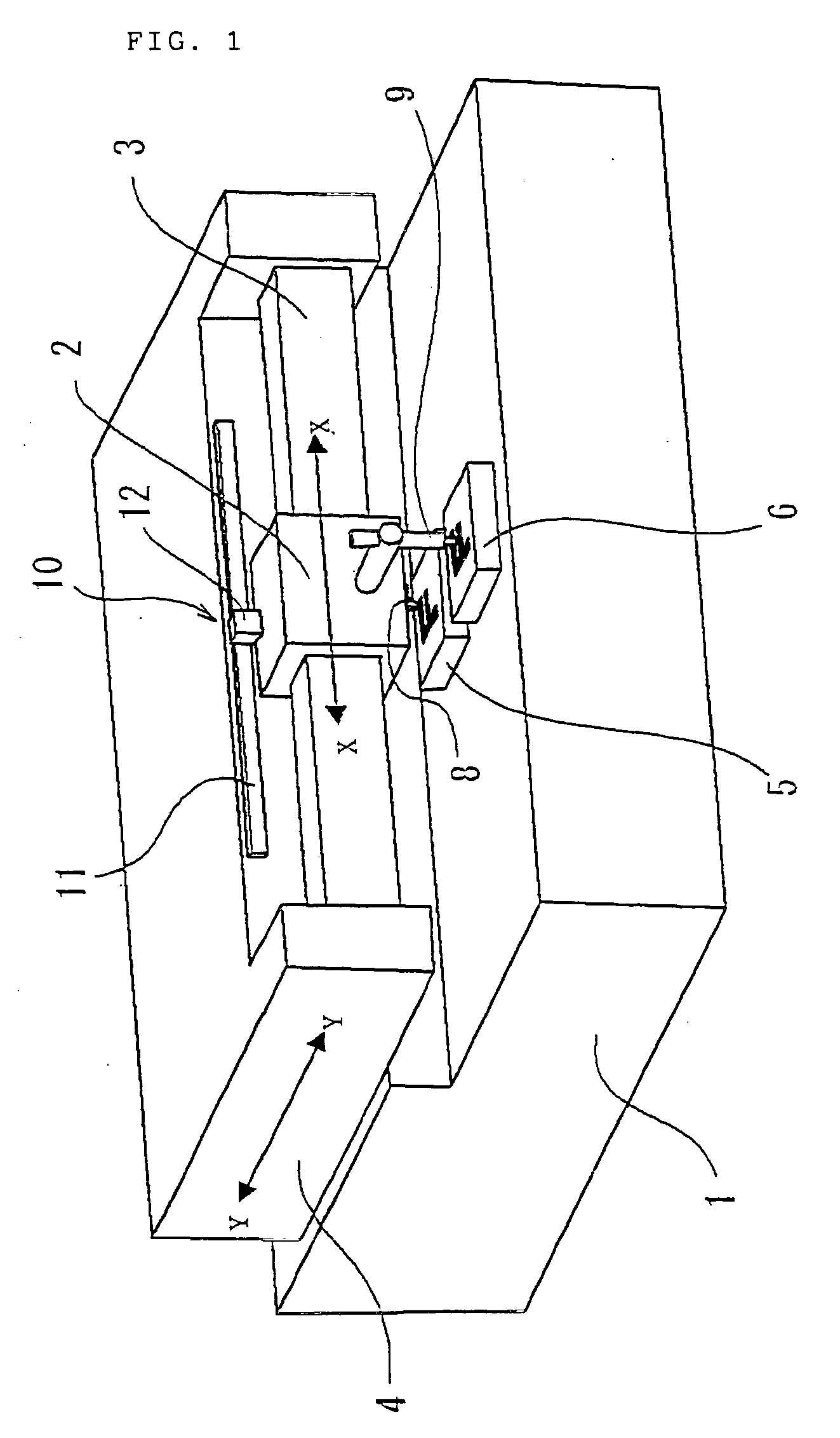
[0030] First, a general description of an embodiment of the inventive machining apparatus will be given with reference to FIG. 1.

[0031] The machining apparatus comprises a first member and a second member that are vertically opposite to each other, and a linear driving means that linearly moves the first member relative to the second member. In the machining apparatus in this embodiment, the second member (base 1) is fixed, the first member 2 (hereinafter referred to as XY movable member) is movable in mutually orthogonal X-axis and Y-axis directions with respect to the base 1, as shown in FIG. 1, and is moved in these directions by linear driving means. The linear driving means includes a first linear driving means 3 (hereinafter referred to as X-axis driving means) that drives the XY movable member 2 in one direction (the X-axis direction) and a second driving means (hereinafter referred to as Y-axis driving means) that moves a movable member 4 (hereinafter referred to as Y movab...


PUM

PropertyMeasurementUnit
frequencyaaaaaaaaaa
speedaaaaaaaaaa
areaaaaaaaaaaa

Abstract

A pulse generation means that generates a pulse each time an XY movable member moves linearly by a certain amount relative to a base is provided. A workpiece and a light and dark pattern member are provided on the base. A tool, a light and dark pattern scanning sensor that scans the light and dark pattern and outputs a scanning signal, and a cutting means that moves the tool with respect to the workpiece in a cutting depth direction, orthogonal to the linear motion direction, are provided on the XY movable member. While the XY movable member moves relative to the base, the tool is moved by the cutting means in accordance with a logical AND operation performed on the scanning signal from the light and dark pattern scanning sensor and the pulse from the pulse generation means to perform machining.

Description

BACKGROUND OF THE INVENTION [0001] 1. Field of the Invention [0002] This invention relates to a precision machine tool and to a machining apparatus that performs high precision machining. [0003] 2. Description of the Related Art [0004] To create a die for molding a light guide plate of the type used for backlighting in a liquid crystal display, tens to hundreds of thousands of minute dimples (hemispherical hollows) need to be machined on the surface of a workpiece. The dimples have a diameter of tens to hundreds of micrometers and are conventionally created one by one by cutting with a machine tool. To perform the cutting, it is necessary to repeat a procedure that includes high speed driving of a small-diameter ball end mill, horizontal positioning of the X and Y axes of the machine tool, and cutting in the Z-axis direction to create a hemispherical dimple. Sometimes the machining is done by a laser machine, in which case some tens of dimples can be machined per second. [0005] A pa...

Claims


Application Information

Patent Timeline
Patent Type & Authority Applications(United States)
IPC IPC(8): B23C3/00B23Q15/00B23Q35/128
CPCB23Q35/128G05B2219/49006Y10T409/300896Y10T409/303192Y10T409/306944Y10T409/303528
Inventor KAWAI, TOMOHIKOEBIHARA, KENZO
Owner FANUC LTD
Why Eureka
Try Eureka