Seat sliding apparatus for vehicle

a technology for sliding apparatus and seats, which is applied in the direction of movable seats, machine supports, roofs, etc., can solve the problems of uncomfortable seating, inability to completely prevent the deflection of the bracket on the outer side of the seat, and inconvenient seating

Inactive Publication Date: 2007-04-26
AISIN SEIKI KK
View PDF1 Cites 12 Cited by
  • Summary
  • Abstract
  • Description
  • Claims
  • Application Information

AI Technical Summary

Benefits of technology

[0008] According to an aspect of the present invention, a seat sliding apparatus for a vehicle includes a lower rail fixed to a vehicle floor, an upper rail fixed to a vehicle seat and supported by the lower rail so as to be movable relative thereto, and a lock mechanism. The lock mechanism includes multiple lock portions provided at the lower rail along a longitudinal direction thereof a lock member provided at the upper rail and rotating a

Problems solved by technology

For example, when an occupant swings a seat in the longitudinal direction of a vehicle or a small acceleration is applied to a seat while a vehicle is running, the bracket may slightly deflect, which may lead to uncomfortable seating.
However, the deflection of the bracket on an outer side thereof cannot be completely prevented.
Thus, when an occupant swings a seat in the l

Method used


Image

  • Seat sliding apparatus for vehicle
  • Seat sliding apparatus for vehicle
  • Seat sliding apparatus for vehicle

Examples


first embodiment

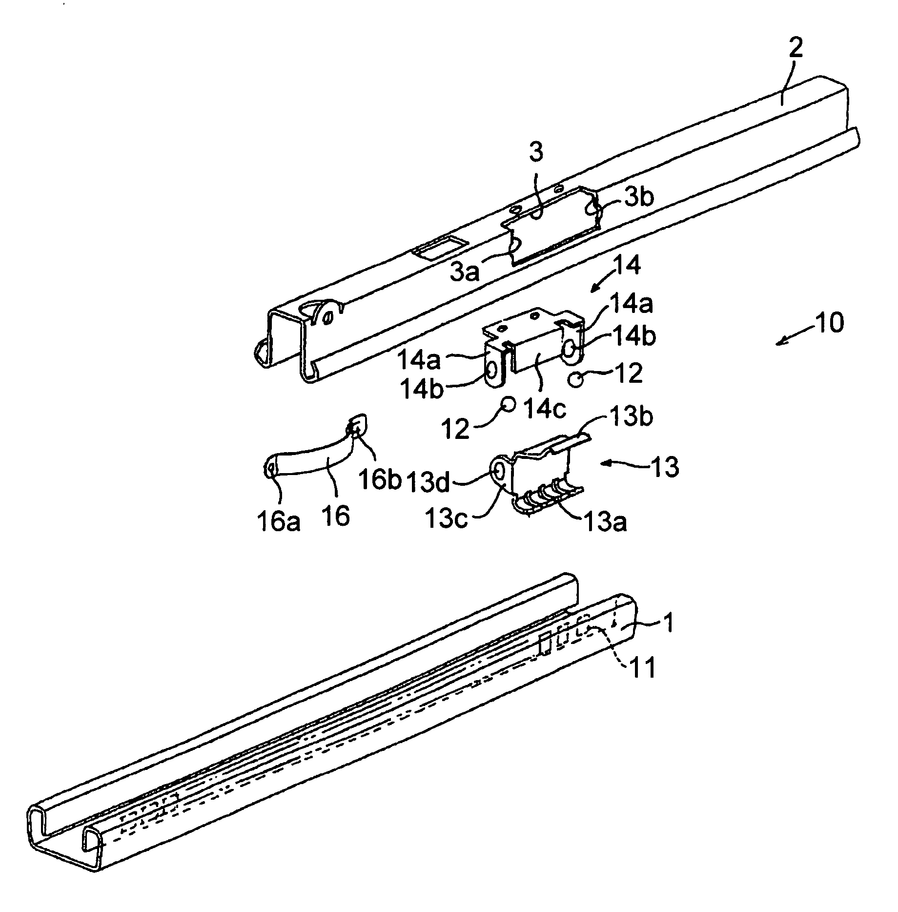
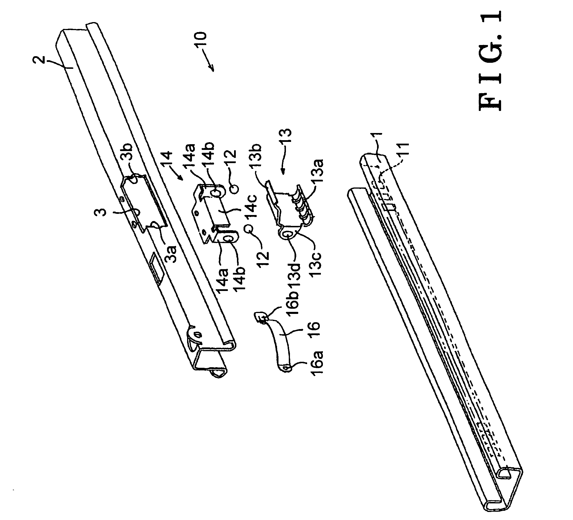
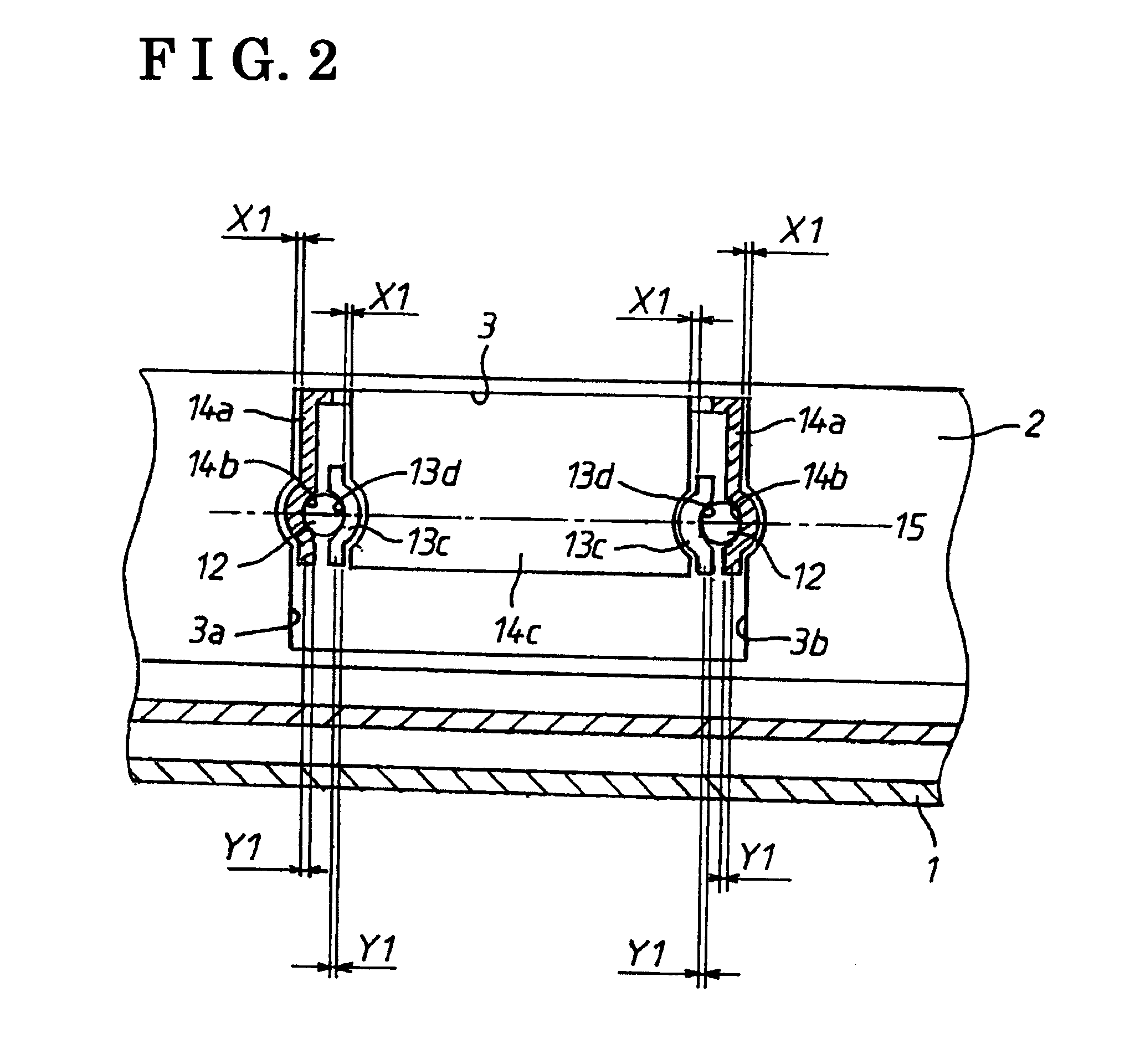
[0020] Embodiments of the present invention will be explained with reference to the attached drawings. FIGS. 1 and 2 show a seat sliding apparatus for a vehicle according to a The seat sliding apparatus for a vehicle includes a pair of lower rails 1 fixed to a vehicle floor 90 on both sides in a width direction, respectively, and a pair of upper rails 2 fixed to a vehicle seat 80 on both sides in the width direction, respectively and supported by the lower rails 1 so as to be movable relative thereto in a vehicle longitudinal direction as shown in FIG. 10. Further, as shown in FIGS. 1 and 2, the seat sliding apparatus for a vehicle includes a lock mechanism 10 provided between each lower rail 1 and each upper rail 2. In FIG. 1, only the upper rail, the lower rail, and the lock mechanism of a one side of the vehicle seat are illustrated. A similar arrangement exists on the other side of the vehicle seat.

[0021] Multiple lock bores 11 that constitute the lock mechanism 10 are formed o...

third embodiment

[0041] According to the seat sliding apparatus having the aforementioned structure, the end faces 23a and 23b are formed so as to face the support plates 34a of the bracket 34, respectively. Thus, the deflection of the bracket 34 in the longitudinal direction of the upper rail 20 (on an outer side) can be restricted. The deflection of the bracket 34 in the longitudinal direction of the upper rail 20 (on an inner side) can be restricted by the spindle 32. Further, the tapered faces 32a are formed on both ends of the spindle 32 so as to engage with the respective engagement bores 34b with no gaps therebetween. Therefore, the movement of the lock lever 33 in the longitudinal direction of the upper rail 20 can be restricted, thereby preventing the looseness of the lock lever 33. The comfortable seating feeling can be ensured according to the

[0042] As shown in FIG. 6, the support plates 34a of the bracket 34 face the end faces 23a and 23b of the hole 23, respectively, while each having a...


PUM


Abstract

A seat sliding apparatus for a vehicle includes a lower rail fixed to a vehicle floor, an upper rail fixed to a vehicle seat and supported by the lower rail so as to be movable relative thereto, and a lock mechanism. The lock mechanism includes multiple lock portions provided at the lower rail along a longitudinal direction thereof, a lock member provided at the upper rail and rotating about a rotation axis extending in a longitudinal direction of the upper rail so as to be engageable with or disengageable from the lock portions, and a bracket for supporting the lock member in a direction of the rotation axis. The seat sliding apparatus for a vehicle further includes a deflection preventing member for preventing a deflection of the bracket in the direction of the rotation axis and being integrally provided at the upper rail.

Description

CROSS REFERENCE TO RELATED APPLICATIONS [0001] This application is based on and claims priority under 35 U.S.C. § 119 to Japanese Patent Application No. 2005-308891, filed on Oct. 24, 2005, the entire content of which is incorporated herein by reference. FIELD OF THE INVENTION [0002] This invention generally relates to a seat sliding apparatus for a vehicle. BACKGROUND [0003] Known seat sliding apparatuses for a vehicle are disclosed in JP2001-47896A and JP11-286230A. The seat sliding apparatus for a vehicle disclosed in JP2001-47896A includes a lower rail fixed to a vehicle floor, an upper rail fixed to a vehicle seat and supported by the lower rail so as to be movable relative thereto, and a lock mechanism. The lock mechanism includes multiple lock portions provided at the lower rail along a longitudinal direction thereof a lock member provided at the upper rail and rotatable about a rotation axis extending in a longitudinal direction of the upper rail so as to be engageable with ...

Claims


Application Information

Patent Timeline
IPC IPC(8): F16M13/00
CPCB60N2/0705B60N2/0818B60N2/0843
Inventor KOJIMA, YASUHIRO
Owner AISIN SEIKI KK
Why Eureka
Try Eureka