
Method for gesture detection on a capacitive touchpad

Inactive Publication Date: 2007-04-26
ELAN MICROELECTRONICS CORPORATION
View PDF3 Cites 17 Cited by
  • Summary
  • Abstract
  • Description
  • Claims
  • Application Information

AI Technical Summary

Benefits of technology

[0005] An object of the present invention is to provide a gesture detection method for a touchpad to prevent the operation of the touchpad from noise interference.

Problems solved by technology

However, these two detection methods might be interfered by external noise, which will cause erroneous determination and accordingly operation that is not desired or predicted.
It results in inconvenience that the drag is often over the range of the touchpad 100 and thus the user needs to repeat the operation several times for a wide drag range.

Method used


Image

  • Method for gesture detection on a capacitive touchpad
  • Method for gesture detection on a capacitive touchpad
  • Method for gesture detection on a capacitive touchpad

Examples


Embodiment Construction

[0022] In a detection method for a capacitive touchpad, according to the present invention, the noise resistive capability of the touchpad is enhanced without any improvement on the hardware detection circuit of the touchpad, and a gesture for operation on the touchpad can be detected by such method.

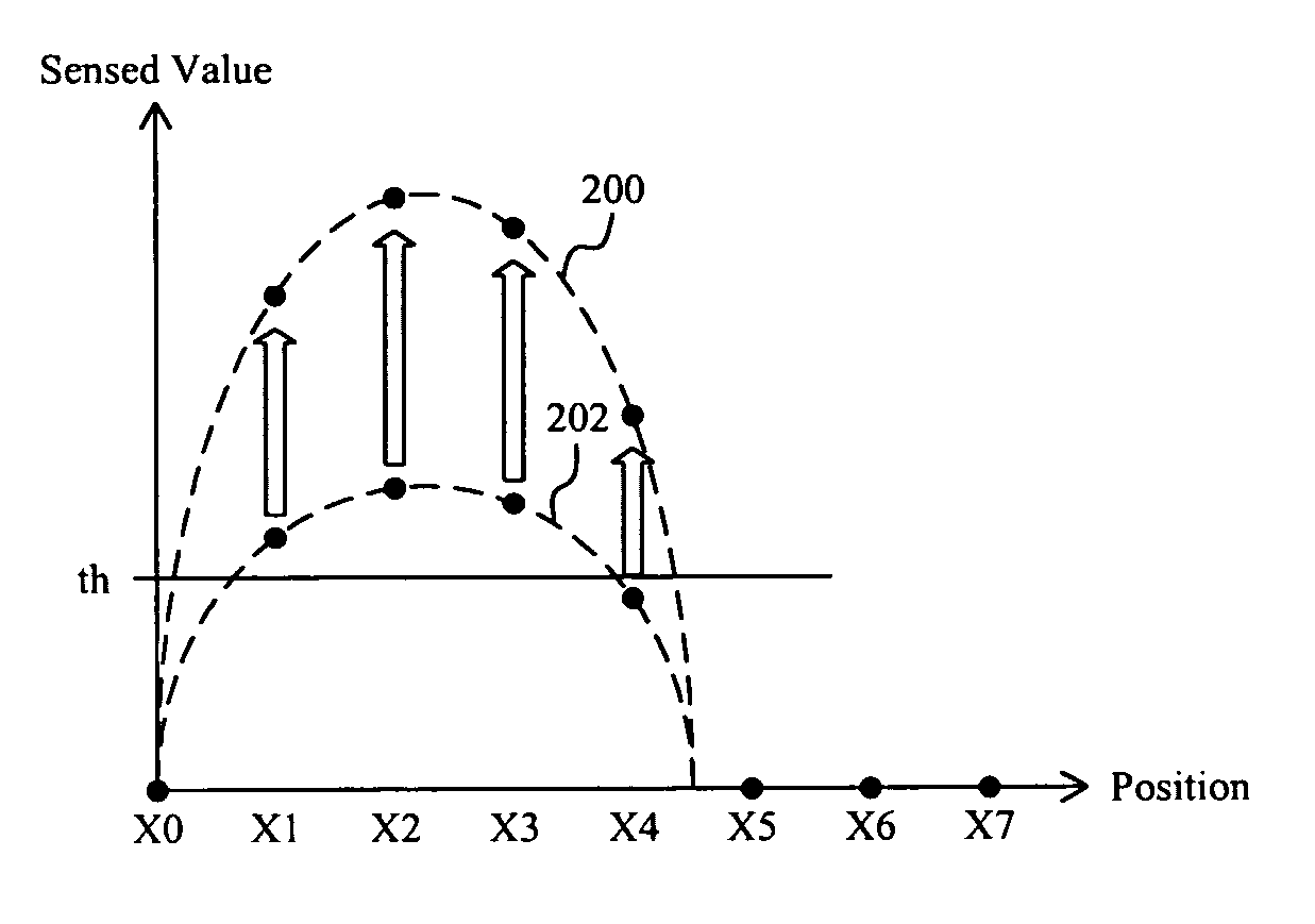
[0023] In FIG. 5, it is shown a variation of the sensed value on the touchpad 100 of FIG. 1 when the sensed value becomes greater than a down threshold th, in which curve 200 represents the sensed value at this time and curve 202 represents the sensed value at the last time. FIG. 6 shows the difference between the sensed values 200 and 202 of FIG. 5, and FIG. 7 shows a detected signal 204. In a detection of the sensed value on the touchpad 100, when the sensed value is detected greater than the down threshold th as shown in FIG. 5, the detected signal 204 will transit from low to high as shown in FIG. 7, and then, within a reference time interval TDownDetect, the sensed value on the tou...


PUM


Abstract

In a gesture detection method for a capacitive touchpad, various gesture operations are determined by detecting the touching on the touchpad, leaving from the touchpad, and moving on the touchpad.

Description

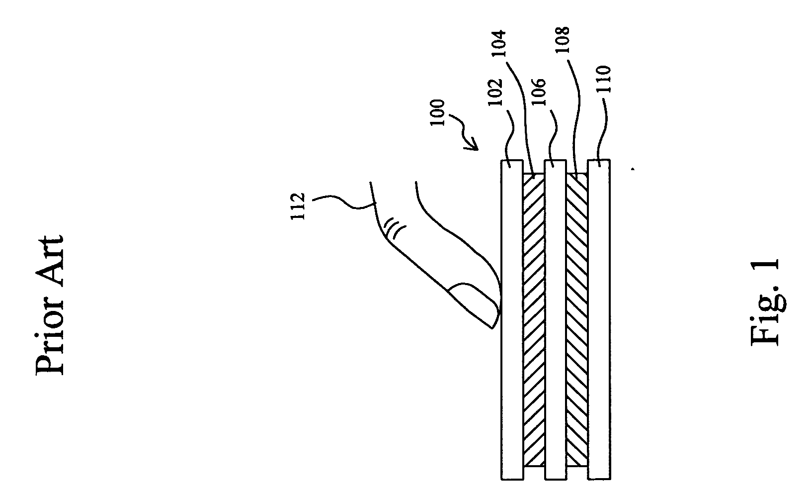
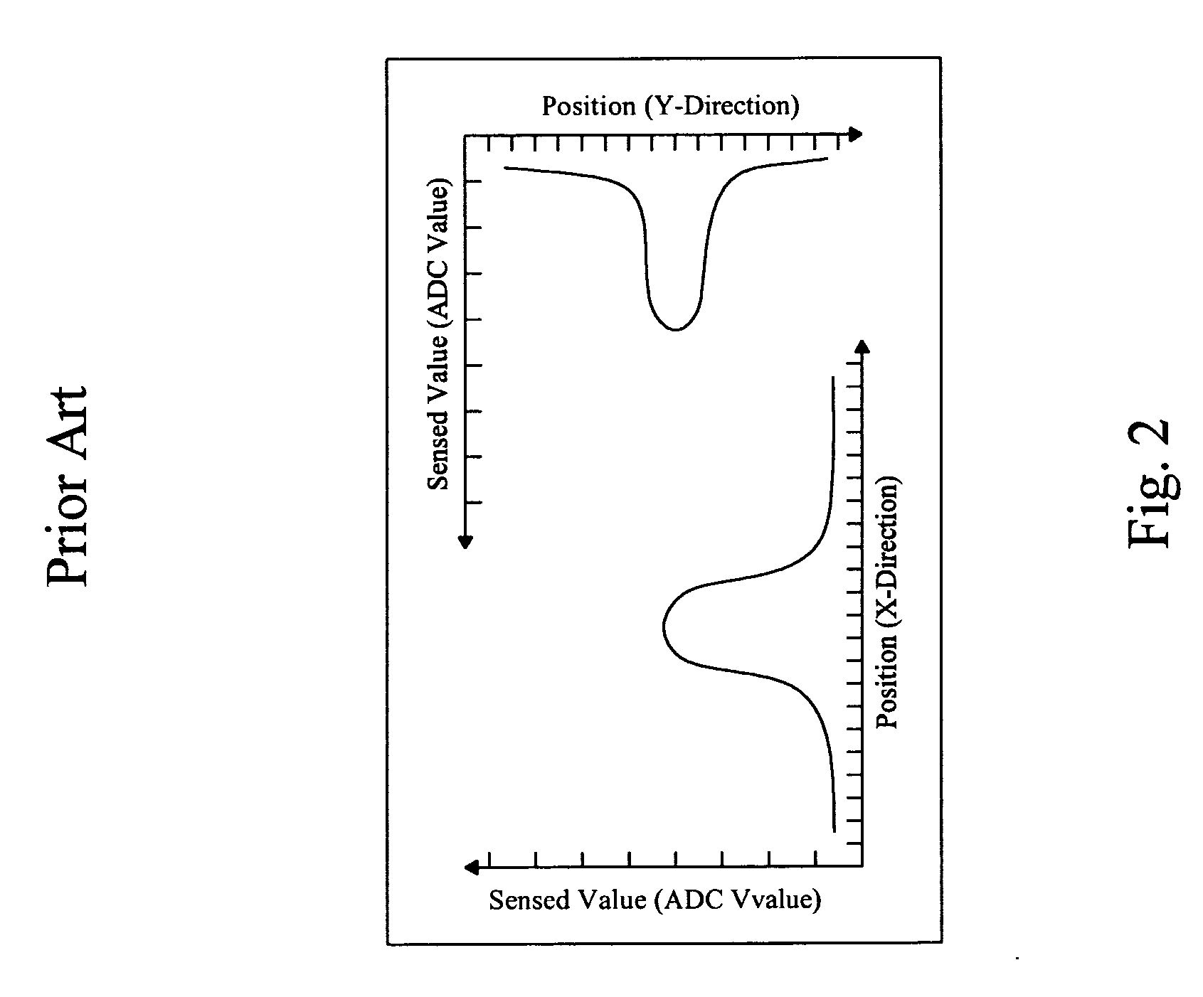
FIELD OF THE INVENTION [0001] The present invention is related generally to a touchpad and, more particularly, to a method for gesture detection on a capacitive touchpad. BACKGROUND OF THE INVENTION [0002] Capacitive touchpad is an input device that allows user to slide his finger on a smooth panel thereof for cursor movement control. Because of its very small thickness, capacitive touchpad can be designed in slim notebooks, keyboards, digital media players and other devices, and moreover, due to its non-mechanical design it is virtually maintenance free. [0003]FIG. 1 shows a cross-sectional view of a conventional two-dimensional capacitive touchpad 100, which comprises a panel 102, a Y-axial sensing layer 104, an insulating layer 106, an X-axial sensing layer 108, and a bottom plate 110. When a finger 112 touches on the panel 102, the sensed values (to the capacitances of the traces in the touchpad 100) on the touched position will vary, and the control circuit connected to the tou...

Claims


Application Information

Patent Timeline
IPC IPC(8): G09G5/00
CPCG06F3/044G06F3/04883G06F3/04186
Inventor LII, JIA-YIHCHIEN, YUNG-LIEH
Owner ELAN MICROELECTRONICS CORPORATION
Learn More