
Regulator pin structure and regulator with the same, structure of balance with hairspring, and mechanical timepiece

a technology of hairspring and regulator, which is applied in the direction of frequency setting mechanism, instruments, and horology, can solve the problems of cumbersome adjustment work, cumbersome assembling process, and potential deformation of hairspring, and achieve the effect of easy free fitting

Inactive Publication Date: 2007-04-26
SEIKO INSTR INC
View PDF9 Cites 31 Cited by
  • Summary
  • Abstract
  • Description
  • Claims
  • Application Information

AI Technical Summary

Benefits of technology

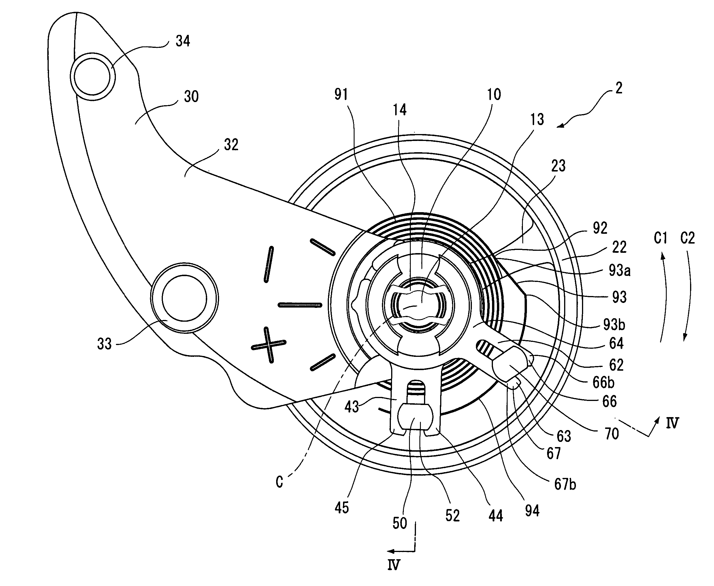
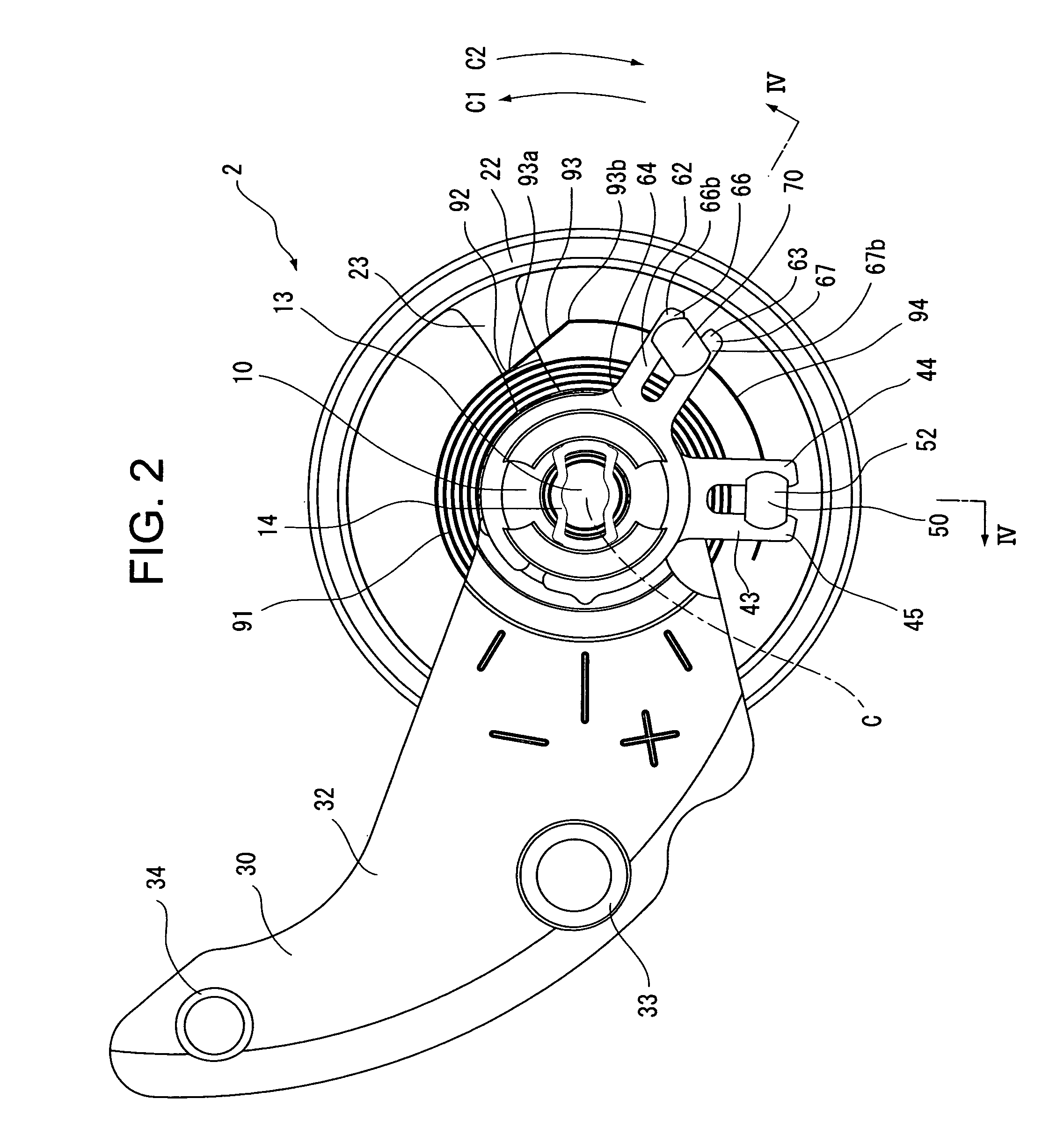
[0014] That is, in the regulator pin structure of the invention, as the distance between the legs including canopy-like projections can be sufficiently larger than the thickness of the outer circumferential portion of the hairspring, the hairspring is freely fitted between the legs of the regulator pin structure without difficulty and subsequent adjustment of the angle of pivotal movement of the regulator pin structure can set a structure of balance with hairspring.
[0021] In the regulator pin structure of the invention, the canopy-like projection is typically formed on both side edges of the front portions of the both legs. This allows the canopy-like projections to prevent the hairspring from being released independent of the direction in which the regulator pin is pivoted and independent of the direction in which the spiral of the hairspring is wound.
[0023] Therefore, in the regulator pin structure of the invention, as described above, the canopy-like projection is typically formed by wiper cutting. Also, in the regulator pin structure of the invention, canopy-like projections at the same side edge of the both legs typically have the same size and shape (mirror symmetry). However, if desired, the left and right canopy-like projections may have asymmetric shapes. In this case, the boundary between the canopy-like projection and the leg is inclined to the side of the leg that faces toward the gap between the legs. Therefore, when the regulator pin structure is pivoted such that the outer end of the hairspring extends diagonally with respect to the gap, such a canopy-like projection easily prevent the hairspring from being released from the front opening of the gap in a reliable manner.
[0026] The structure of balance with hairspring of the invention is configured such that, when the regulator pin structure is pivoted around its center axis, the canopy-like projection prevents the hairspring from being released from the gap.

Problems solved by technology

However, since this proposed regulator pin structure (although it is described (termed) as a “regulator key” in the U.S. Pat. No. 4,083,179, it is herein referred to as a regulator pin structure) is configured such that the tips of the pair of legs are bent inward to be closer to each other, when the gap between the tips is narrowed in order to prevent the outer end of the hairspring from being released, it is required to open the gap between the tips of the legs and forcibly push the hairspring therein for assembling, resulting in a cumbersome assembling process and also a potential accidental deformation of the hairspring.
Also, in this proposed regulator pin structure, since the tips of the legs are hammered to bend-them inward, not only may the legs of the regulator pin structure be deformed to a certain extent when they undergo the bending process so that the deformation may affect the behavior of the hairspring in a measurable manner but also variation among individual regulator pin structures may be large, resulting in potential cumbersome adjustment work.
Also, it is difficult to automatically carry out this bending process without a dedicated processing machine and practically difficult to manufacture the regulator pin structure with a continuous processing system using a general purpose numerically-controlled machining tool.

Method used


Image

  • Regulator pin structure and regulator with the same, structure of balance with hairspring, and mechanical timepiece
  • Regulator pin structure and regulator with the same, structure of balance with hairspring, and mechanical timepiece
  • Regulator pin structure and regulator with the same, structure of balance with hairspring, and mechanical timepiece

Examples


Embodiment Construction

[0036] A preferred embodiment of the invention will be described with reference to a preferred example shown in accompanied drawings.

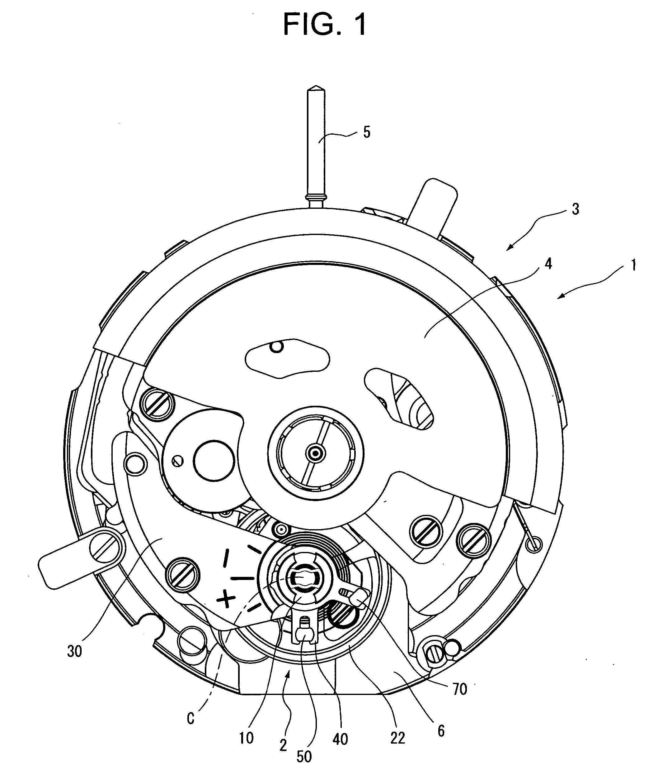
[0037]FIG. 1 shows a mechanical timepiece 1 of a preferred example according to the invention. In FIG. 1, only the mechanical timepiece 1 without the exterior, that is, a movement 3 is shown. The movement 3 of the timepiece 1 includes a structure of balance with hairspring 2 as a speed governor. Although the movement 3 of the timepiece 1 shown in FIG. 1 is a movement with an oscillating weight 4 for a self-winding timepiece, the movement 3 may be a manual-winding movement with a winding stem 5. The movement 3 of the mechanical timepiece 1 shown in FIG. 1 is by way of example only, and the detailed structure of the movement 3 may be any other structures.

[0038] As shown in FIGS. 2 to 4, the structure of balance with hairspring 2 of the preferred example according to the invention has a balance staff 21 that is supported between an upper bearing for bal...


PUM


Abstract

There is provided a regulator pin structure that is not only easily assembled but also capable of holding a hairspring in a gap without a risk of the hairspring being released, a regulator with the regulator pin structure, a structure of balance with hairspring, and a mechanical timepiece. A regulator pin structure of a regulator that is a component of a structure of balance with hairspring of a mechanical timepiece includes a pin-like body, a base that is situated on one end of the body and mounted to a body of regulator such that the position of the base is adjustable around the pivotal center axis E of the body, and a pair of two-pronged legs that extend from the other end of the body. The regulator pin structure is configured such that part of the outer end of a hairspring that is situated beyond a reformed portion of the hairspring along the outer circumference direction is freely fitted in a gap between the legs. Canopy-like projections are formed on at least one side edge of the front portion of at least one of the pair of legs in such a manner that the canopy-like projections laterally project along sides of the legs that face toward the gap. Regulator pin structure and regulator with the same, structure of balance with hairspring, and mechanical timepiece

Description

BACKGROUND OF THE INVENTION [0001] 1. Field of the Invention [0002] The present invention relates to a regulator pin structure and a regulator with the same, a structure of balance with hairspring, and a mechanical timepiece. [0003] 2. Description of the Prior Art [0004] A regulator with “a regulator pin structure including a pin-like body, a base that is situated on one end of the body and mounted to a body of regulator such that the position of the base is adjustable around the pivotal center axis of the body, and a pair of two-pronged legs that extend from the other end of the body, the regulator pin structure being configured such that part of the outer end of a hairspring that is situated beyond a reformed portion of the hairspring along the outer circumference direction is freely fitted in a gap (slit) between the pair of legs” is well known and has been conventionally used for numerous mechanical timepieces. [0005] While this regulator pin structure has an advantage that its ...

Claims


Application Information

Patent Timeline
IPC IPC(8): G04B17/20G04B17/04
CPCG04B17/06G04B17/325G04B18/026
Inventor TAKAHASHI, TAKASHI
Owner SEIKO INSTR INC
Learn More