
Anesthesia equipment lift system

Inactive Publication Date: 2007-04-26
INTELLIVET ANESTHESIA EQUIP
View PDF7 Cites 14 Cited by
  • Summary
  • Abstract
  • Description
  • Claims
  • Application Information

AI Technical Summary

Problems solved by technology

As such, during periods in which the anesthesia equipment is not being utilized for inhalation anesthesia, the anesthesia equipment can be an impediment to utilizing the treatment table for other procedures and makes the anesthesia equipment exposed and susceptible to damage by contact.
However, this may not make the anesthesia equipment less susceptible to damage and only serves to place the anesthesia equipment at a less convenient location for subsequent use.

Method used


Image

  • Anesthesia equipment lift system
  • Anesthesia equipment lift system
  • Anesthesia equipment lift system

Examples


Embodiment Construction

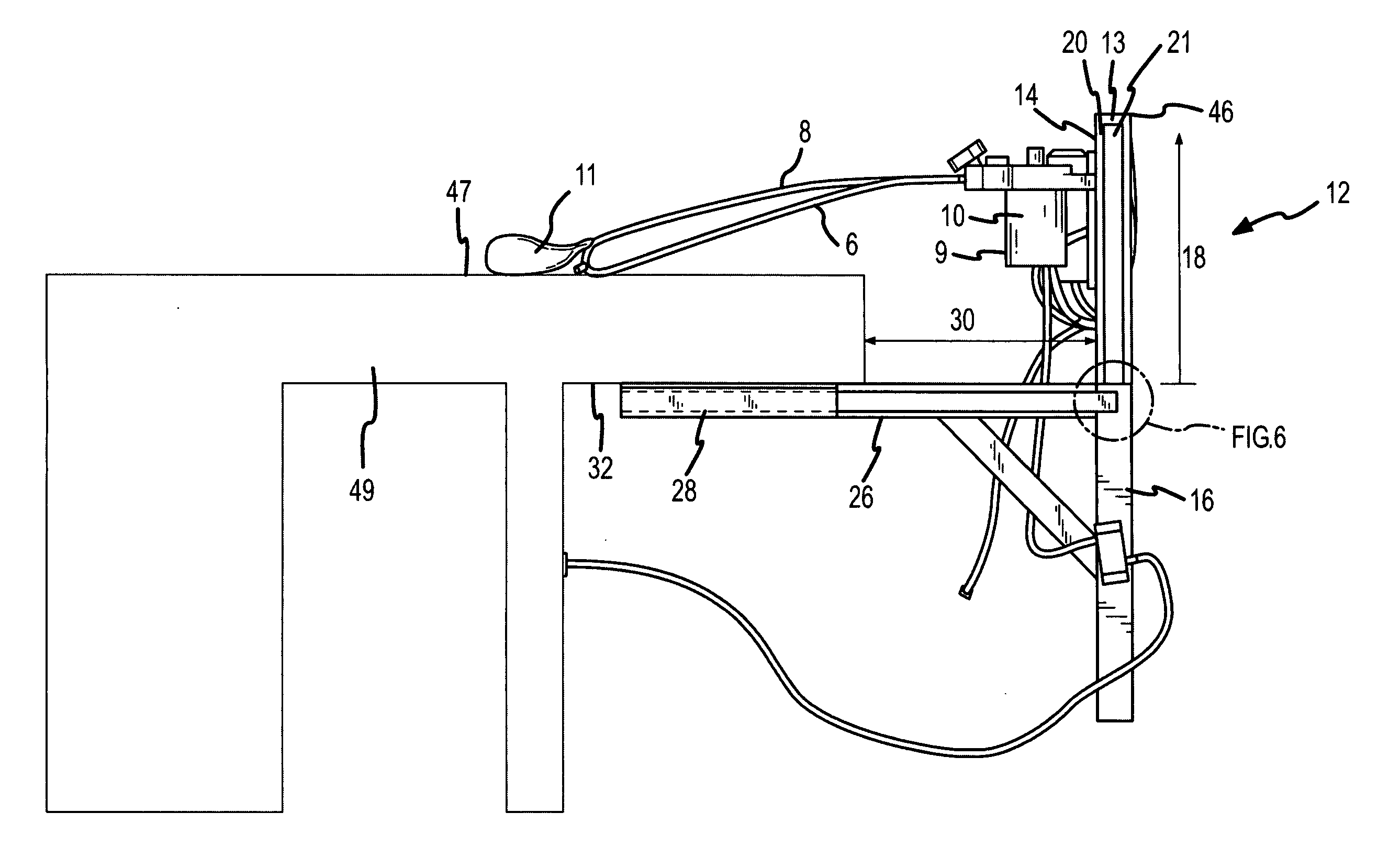
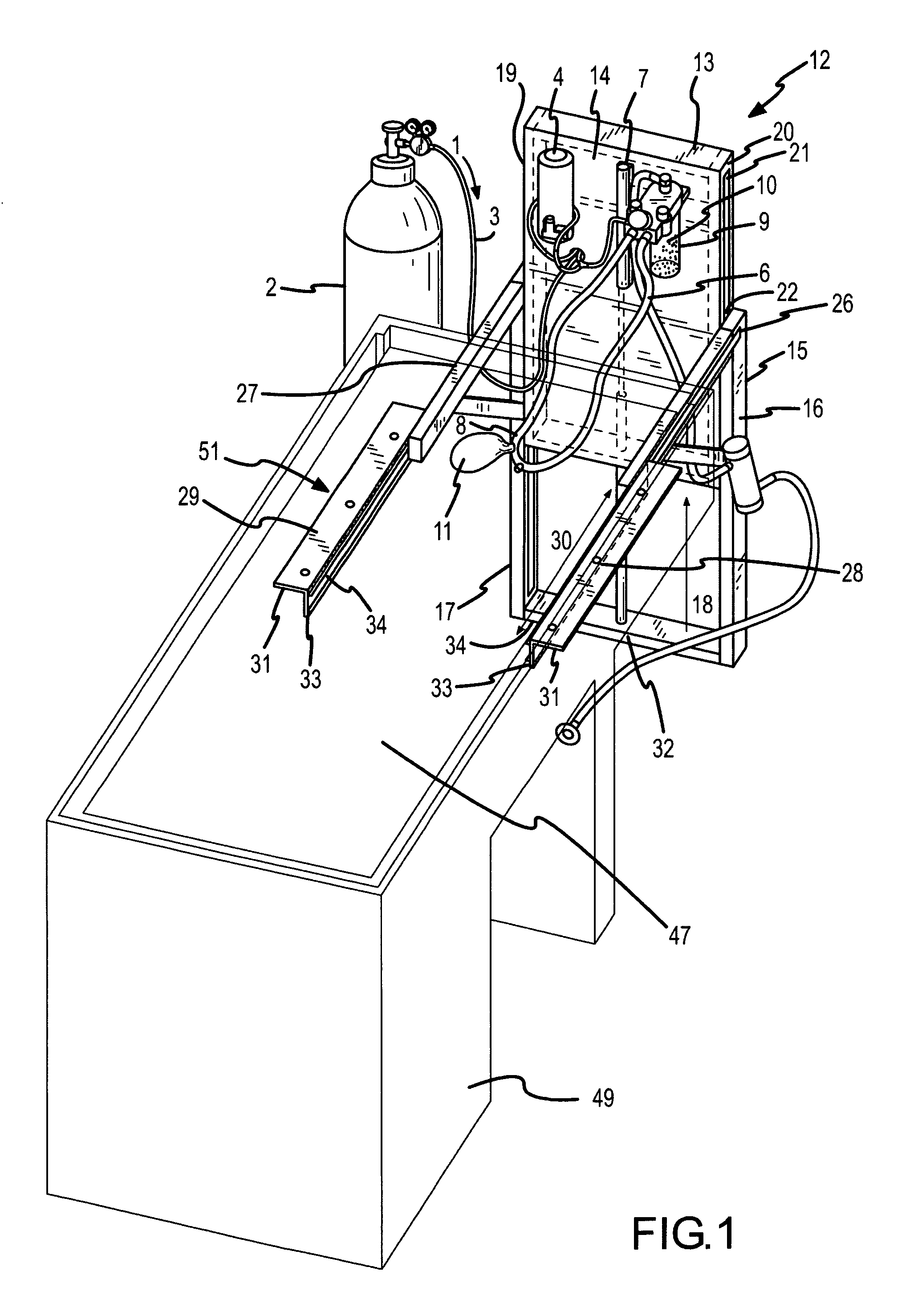
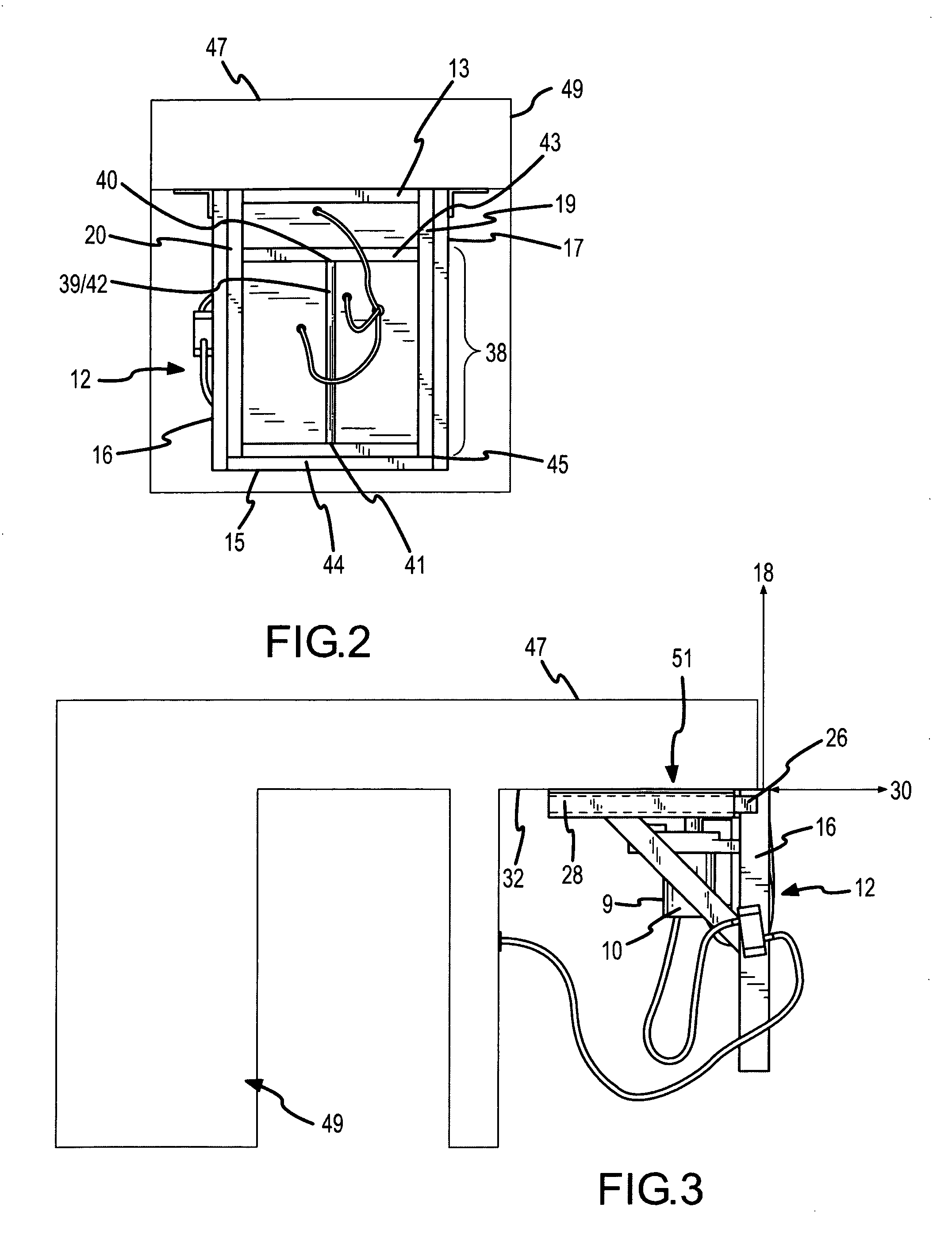
[0015] An anesthesia equipment lift which couples to a table having an anesthesia equipment mount surface coupled to a lift element which travels from a first location to a second location to position mounted inhalation anesthesia equipment proximate to a patient located on the table surface to perform inhalation anesthesia.

[0016] Referring primarily to FIG. 1, a flow of gas (1) can be generated by release of an amount of gas from a pressure regulated compressed gas cylinder (2)(or other type of pressure regulated device) into a gas flow conduit (3) coupled to an anesthetic vaporizer (4). The anesthetic vaporizer (4) contains an amount of the anesthetic and can be adjusted to deliver more or less of the anesthetic to a patient through an inhalation circuit (6). The volume of gas introduced into inhalation circuit (6) can be assessed by observation of a gas flow meter (7) coupled to the flow of gas (1) entering the inhalation circuit (6). The patient inhales the gas in the inhalatio...


PUM


Abstract

An anesthesia equipment lift which couples to a table to provide an anesthesia equipment mount surface coupled to a lift element which travels from a first location to a second location to position mounted inhalation anesthesia equipment proximate to a patient located on the table surface to perform inhalation anesthesia.

Description

[0001] This United States Non-provisional Patent Application claims the benefit of U.S. Provisional Patent Application No. 60 / 730,487, hereby incorporated by reference herein.I. BACKGROUND [0002] An anesthesia equipment lift which couples to a table to provide an anesthesia equipment mount surface coupled to a lift element which travels from a first location to a second location to position mounted inhalation anesthesia equipment proximate to a patient located on the table surface to perform inhalation anesthesia. [0003] Inhalation anesthesia equipment must be located proximate to the patient on the treatment table during inhalation anesthesia. In conventional practice, the anesthesia equipment may be mounted at fixed location proximate to the table surface. As such, during periods in which the anesthesia equipment is not being utilized for inhalation anesthesia, the anesthesia equipment can be an impediment to utilizing the treatment table for other procedures and makes the anesthe...

Claims


Application Information

Patent Timeline
IPC IPC(8): A61M31/00
CPCA61G13/10A61M16/0078A61M16/01A61M16/22A61M2209/084
Inventor LEONARD, ROBERT DEAN
Owner INTELLIVET ANESTHESIA EQUIP
Learn More