
Viewport panning feedback system

Inactive Publication Date: 2007-05-03
138 EAST LCD ADVANCEMENTS LTD
View PDF19 Cites 78 Cited by
  • Summary
  • Abstract
  • Description
  • Claims
  • Application Information

AI Technical Summary

Benefits of technology

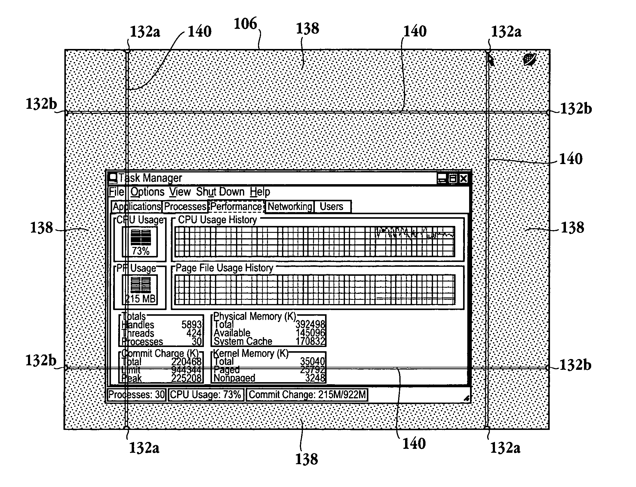
[0010] In yet another embodiment, a computing device configured to interact with other computing devices is provided. The computing device includes a central processing unit (CPU) and a memory storing a sharing application. The sharing application enables the computing device to create a virtual link with one of the other computing devices so that input devices of the computing device appear physically connected to another of the computing devices. A display screen configured to display a first portion of image data from the one of the other computing devices within a viewport of the computing device is included. Viewport logic configured to provide multiple visual indicators revealing availability of panning the image data, availability of a panning direction, a relative location of the first portion of the image data within the source content / image data, and a panning rate when moving from the first portion of image data along a panning path to a second portion of the image data is provided. A bus enables communication between the CPU, the memory, the display screen, and the viewport logic.

Problems solved by technology

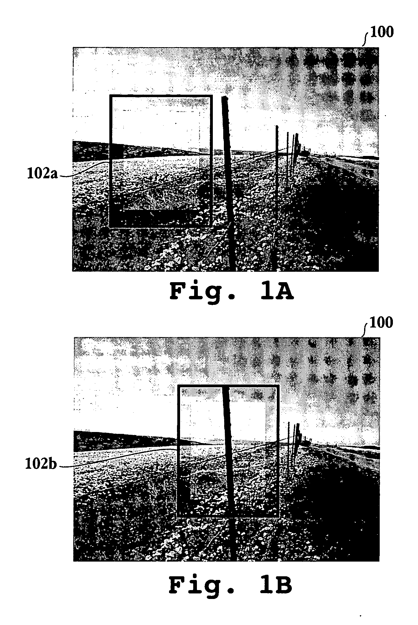
Typically it is difficult or impossible to contain the entire digital content at the required scale within the available display area or window region.
The window containing the viewport window typically provides some means for adjusting the position of the viewport over the source content, thus affecting which portion of the source content is visible in the viewport window.
Each of these techniques has disadvantages, such as, limiting the available viewing area, limited ability to customize control of the panning, limited feedback to the user about the panning operation and other intrusive characteristics.

Method used


Image

  • Viewport panning feedback system
  • Viewport panning feedback system
  • Viewport panning feedback system

Examples


Embodiment Construction

[0025] An invention is described for an apparatus and method that provides visual feedback, which includes dynamic rate and directional information to a computer user during interactive panning of a viewport over a source surface. It will be obvious, however, to one skilled in the art, that the present invention may be practiced without some or all of these specific details. In other instances, well known process operations have not been described in detail in order not to unnecessarily obscure the present invention.

[0026] The embodiments described below provide a graphical user interface (GUI) that enables a user to configure the panning functionality. In addition, the system enabling the GUI is configured to provide visual feedback to a user during interactive panning of the viewport over source image data. In one embodiment, the user is given fine-grained configurable control over the rate of speed and direction of the panning operation. Additionally, all elements of the inventi...


PUM


Abstract

A graphical user interface (GUI) displaying a viewport includes a panning control region defined within an outer boundary of the viewport within the GUI. The panning control region includes multiple segments, each of the multiple segments corresponding to a panning direction, wherein a panning rate is indicated by a level of translucency of the multiple segments. A panning available region defined along the outer boundary of the viewport within the GUI is included. The panning available region indicates whether a source image extends beyond an edge of the viewport, and the panning available region is a subset of the panning control region. A method for panning an image through a viewport and a computing device are also provided.

Description

BACKGROUND OF THE INVENTION [0001] In computer applications, users display and interact with a variety of digital content. This content may include images, video, documents, web pages, applications, or any other information. Often more than one type of content needs to be viewed simultaneously. Windowing systems are employed in graphical operating systems for this purpose. A window defines a region, or area, on a display that will hold a particular digital content. Multiple windows can be defined and can overlap one another for the purpose of sharing a limited display area. [0002] Frequently, it is necessary to display content whose dimensions are larger than any available display, or window region, is capable of containing. Also, in many instances, users need to work with fine details that require magnifying or scaling the digital content. For example, a user may need to magnify a document for legibility, or may need to make precise adjustments to a figure in an engineering or pain...

Claims


Application Information

Patent Timeline
IPC IPC(8): G09G5/00
CPCG06F3/0485
Inventor IVASHIN, VICTORRASMUSSEN, JAMIE C.
Owner 138 EAST LCD ADVANCEMENTS LTD
Learn More