
Expansion anchor

Inactive Publication Date: 2007-05-03
HILTI AG
View PDF8 Cites 11 Cited by
  • Summary
  • Abstract
  • Description
  • Claims
  • Application Information

AI Technical Summary

Benefits of technology

[0012] The expansion anchor has an integrated sealing function. For setting the inventive expansion anchor, the number of operational steps is comparable with setting of a conventional expansion anchor without a seal, so that the inventive anchor can be used almost without any limitations. The demands to the environmental conditions of the site are substantially lower than with sealing with mortar or resin, which substantially increases the application region of the inventive expansion anchor. An important advantage of the inventive expansion anchor also consists in that no specific operational measures are required with the use of the expansion anchor. In addition, the expansion anchor can be used without any problems at an overhead work. Overall, it can be concluded that the inventive expansion anchor can be handled and set substantially easier than a conventional expansion anchor, and it can be economically produced.
[0022] In addition, the elastically deformable components of the seal can compensate possible, thermally induced, dimensional changes of the seal. Advantageously, the seal has, in addition to the elastically deformable components also plastically deformable components.

Problems solved by technology

The drawback of the known expansion anchor consists in that media, e.g., water can penetrate in a gap between the expansion anchor and the borehole wall unhindered, which leads to a corrosion damage of the expansion anchor and, thus, to the reduction of its bearing capacity.
In addition, the corrosion damage can affect the concrete reinforcement that was cut during formation of the borehole, which can lead to the reduction of the bearing capacity of the entire construction.
The drawback of the known solution consists in that several components need be handled, and many steps are necessary for anchoring the anchor.
Further, when mortar is used, in most cases, adherence to particular operational measures is required, which increases operational expenses associated with anchoring of an expansion anchor.
Still further, the storage life of the mortar or at least some of its separate components is limited.
The use of resins instead of mortar for filling the gap between the expansion anchor and the borehole wall, results essentially in the same drawbacks as with using the mortar.

Method used


Image

  • Expansion anchor
  • Expansion anchor
  • Expansion anchor

Examples


Embodiment Construction

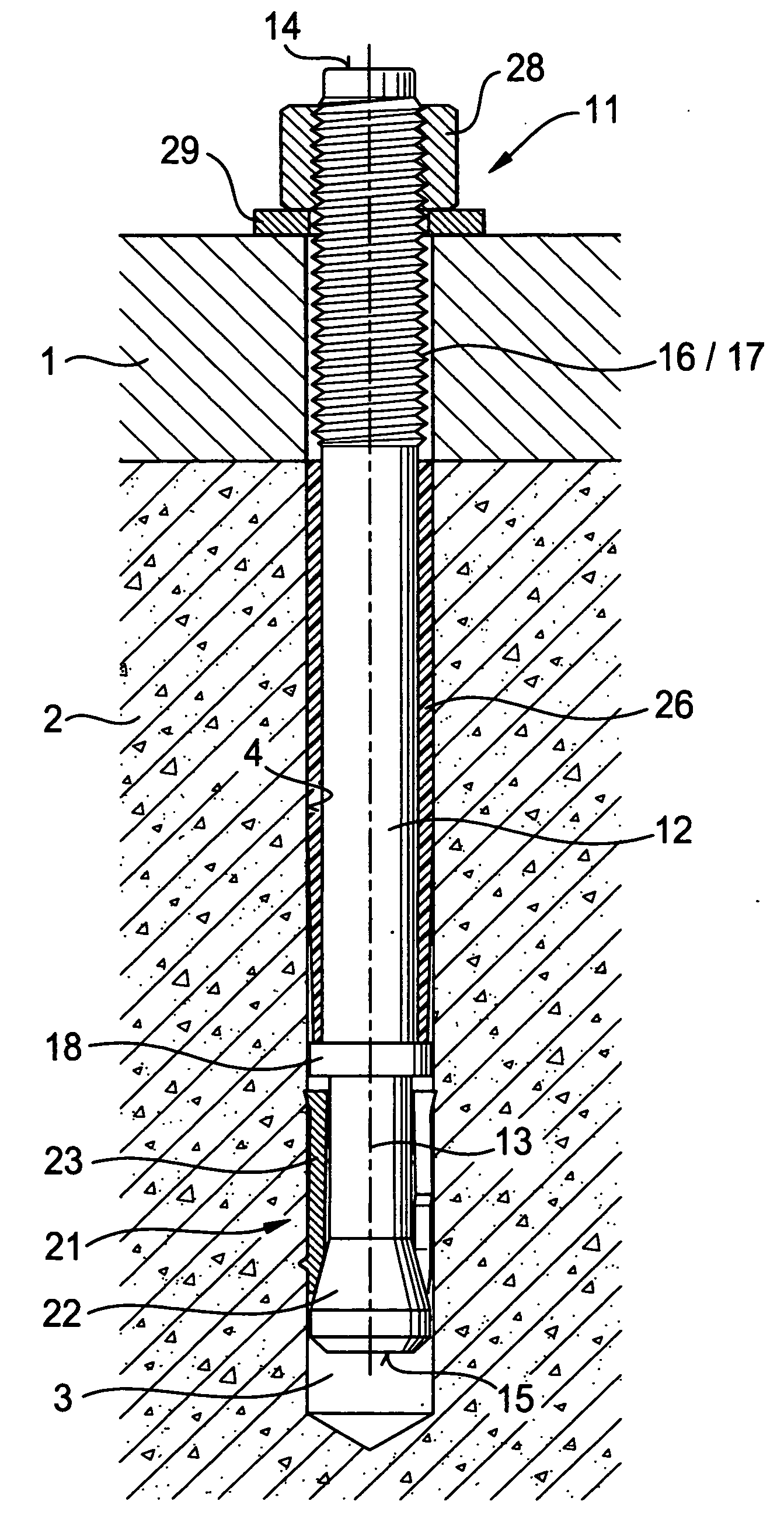
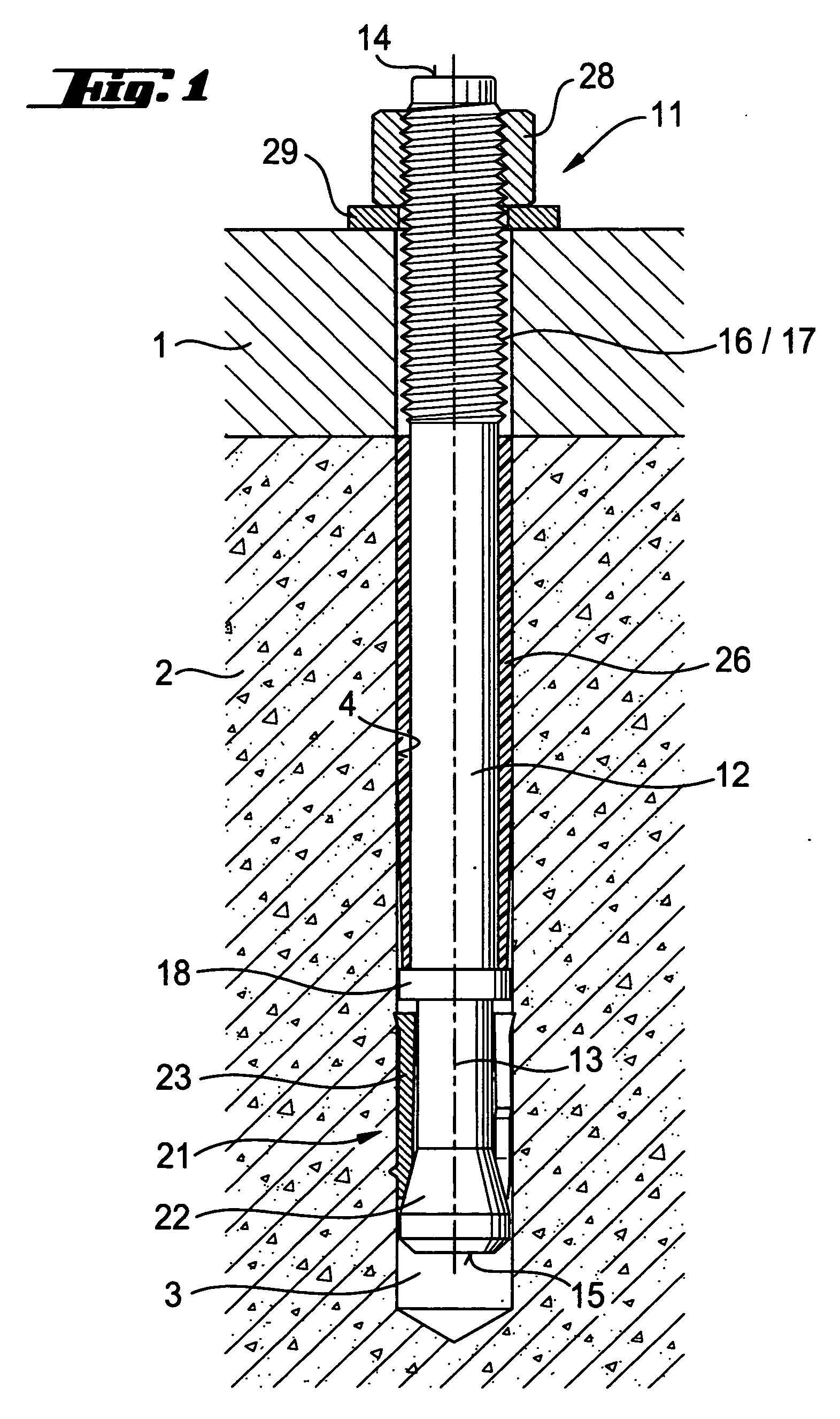
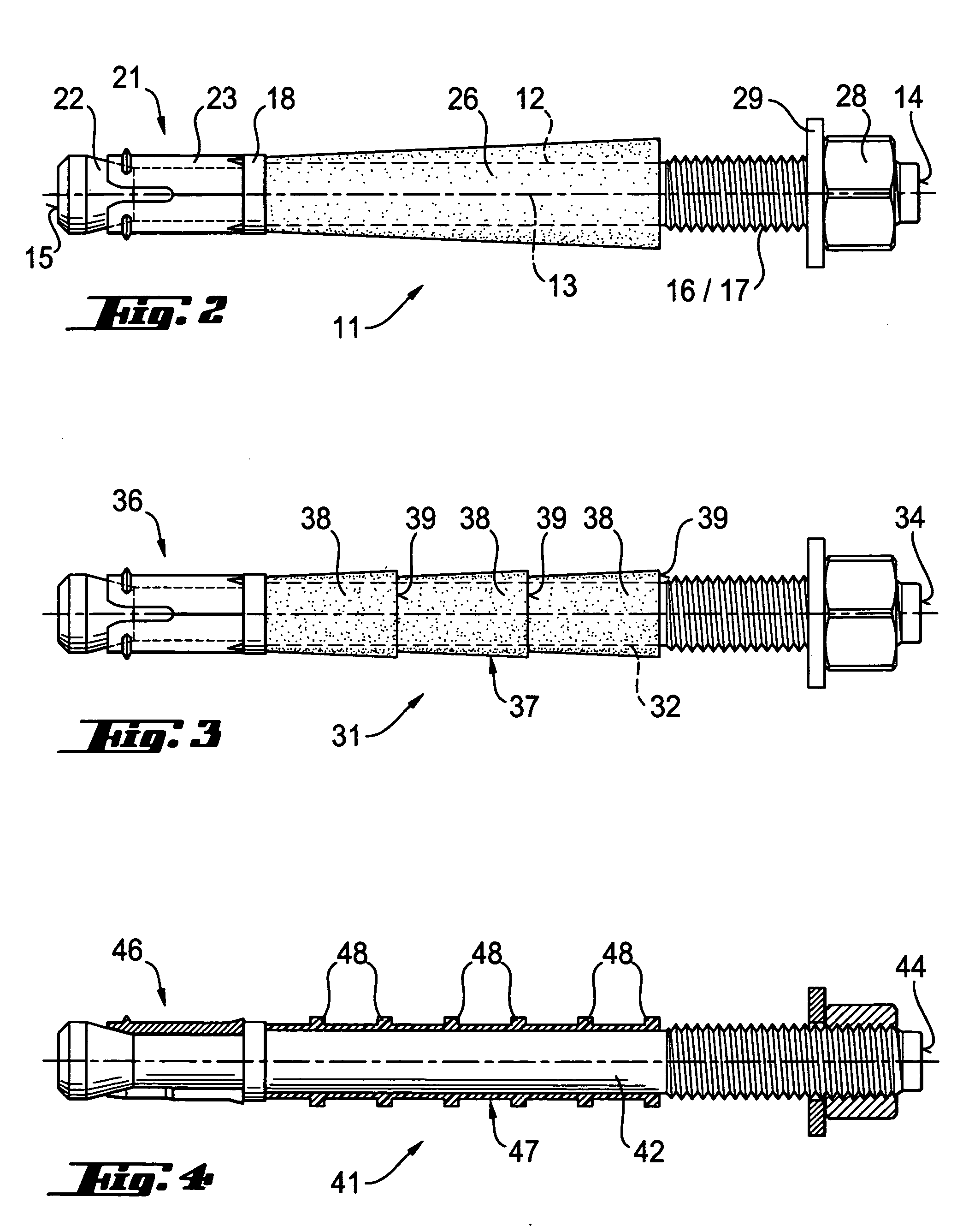
[0037] An expansion anchor 11 according to the present invention, a first embodiment of which is shown in FIGS. 1-2, has a stem 12, a first end 14, and a second end 15 located opposite the first end 14.

[0038] On the stem 12, there is provided an outer thread 17 that extends up to the first end 14 and forms load application means 16. For forming an anchoring mechanism 21, there are provided, on the stem 12, an expansion body 22 that widens toward the second end 15, and an expansion sleeve 23 that at least partially surrounds the expansion body 22 and is expandable thereby.

[0039] The expansion anchor 11 further includes a seal 26 located between the anchoring mechanism 21 and the first end 14 of the stem 12. The seal 26 is formed as a coating and has a different radial extent over its axial extent along an axis 13 of the stem 12. The sealing 26 has, in a direction of the first end 14 along the longitudinal axis 13 of the stem 12, a radially increasing dimension. The seal 26 is forme...


PUM


Abstract

An expansion anchor includes a load application element (16) provided on the stem (12; 32; 42; 52; 62) and extending up to first end (14; 34; 44; 54; 64) of the stem, an anchoring mechanism (21; 36; 46; 56; 66) provided on the stem (12; 32; 42; 52; 62) and a seal (26; 37; 47; 57; 67) arranged between the anchoring mechanism (21; 36; 46; 56; 66) and the first end (14; 34; 44; 54; 64) of the stem (12; 32; 42; 52; 62) and having over its axial extent along a longitudinal axis (13) of the stem (12; 32; 42; 52; 62) different radial dimensions.

Description

BACKGROUND OF THE INVENTION [0001] 1. Field of the Invention [0002] The present invention relates to an expansion anchor which is to be anchored in a borehole and which has a stem having a first end and a second end opposite the first end, load application means provided on the stem and extending up to first end, and an anchoring mechanism provided on the stem. [0003] 2. Description of the Prior Art [0004] German Publication DE 195 41 564 A1 discloses an expansion anchor which is to be anchored in a borehole and which includes a stem having a first and a second end opposite the first end. On the stem, there is provided load application means extending up to the first end. For forming an anchoring mechanism, there are provided, on the stem, an expansion body that widens toward the second end and an expansion sleeve that at least partially surrounds the expansion body and is expandable hereby. [0005] Such expansion anchors are used for securing a constructional part to a constructiona...

Claims


Application Information

Patent Timeline
IPC IPC(8): F16B13/06
CPCF16B13/066F16B13/0858F16B2013/006F16B13/065
Inventor ROSENKRANZ, FALK
Owner HILTI AG
Learn More