
Delivery device with anchoring features and associated method

Active Publication Date: 2007-05-03
MERIT MEDICAL SYST INC
View PDF16 Cites 104 Cited by
  • Summary
  • Abstract
  • Description
  • Claims
  • Application Information

AI Technical Summary

Benefits of technology

[0010] The invention addresses the above needs and achieves other advantages by providing a delivery device for deploying an implantable device within a lumen. The delivery device includes anchors positioned on an inner tube for stabilizing the implantable device during deployment. The anchors provide a compressive force to the implantable device and an outer tube that reduces foreshortening of the device, which also reduces the potential for inaccurately positioning the device within the lumen.
[0011] In one embodiment of the present invention, a delivery device for positioning and deploying an implantable device within a lumen is provided. The device includes a longitudinal outer tube having proximal and distal ends, wherein the implantable device is positioned proximate to the distal end of the outer tube. The device also includes a longitudinal inner tube positioned within the outer tube and having proximal and distal ends, wherein the outer tube is capable of sliding over the inner tube. A mechanism is coupled to the inner and / or outer tubes and is operable to deploy the implantable device within the lumen. At least one anchor is positioned on the inner tube to stabilize the implantable device by engaging at least a portion of the implantable device while the mechanism deploys the device. The anchor is positioned on the inner tube such that the anchor is freely rotatable about the inner tube.

Problems solved by technology

The anchors provide a compressive force to the implantable device and an outer tube that reduces foreshortening of the device, which also reduces the potential for inaccurately positioning the device within the lumen.

Method used


Image

  • Delivery device with anchoring features and associated method
  • Delivery device with anchoring features and associated method
  • Delivery device with anchoring features and associated method

Examples


Embodiment Construction

[0030] The present invention now will be described more fully hereinafter with reference to the accompanying drawings, in which some, but not all embodiments of the invention are shown. Indeed, this invention may be embodied in many different forms and should not be construed as limited to the embodiments set forth herein; rather, these embodiments are provided so that this disclosure will satisfy applicable legal requirements. Like numbers refer to like elements throughout.

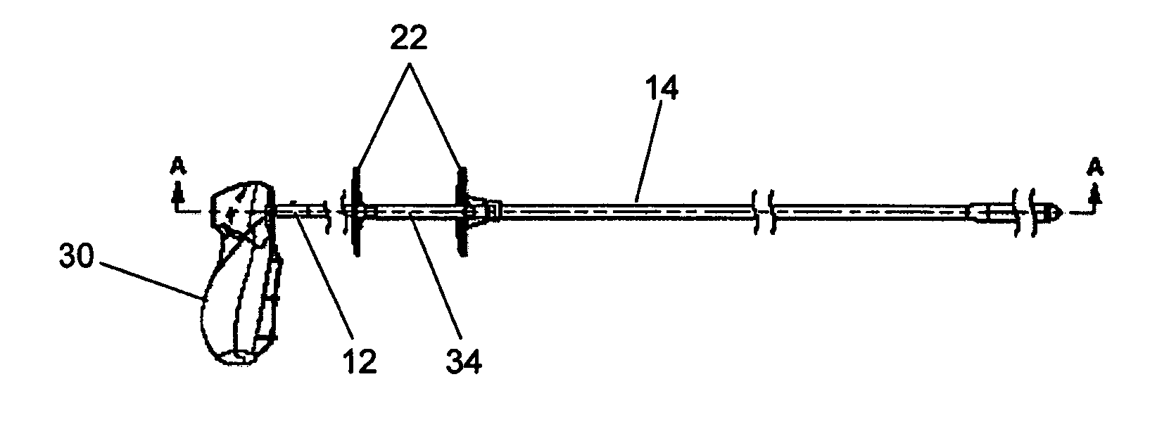
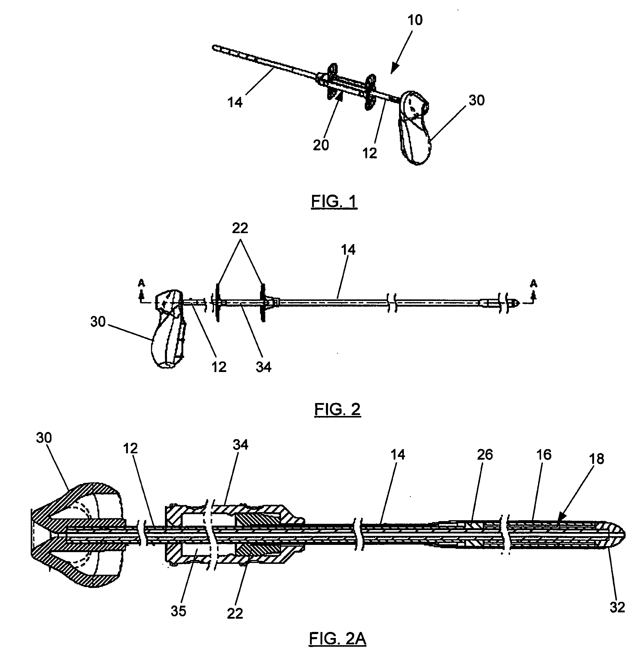
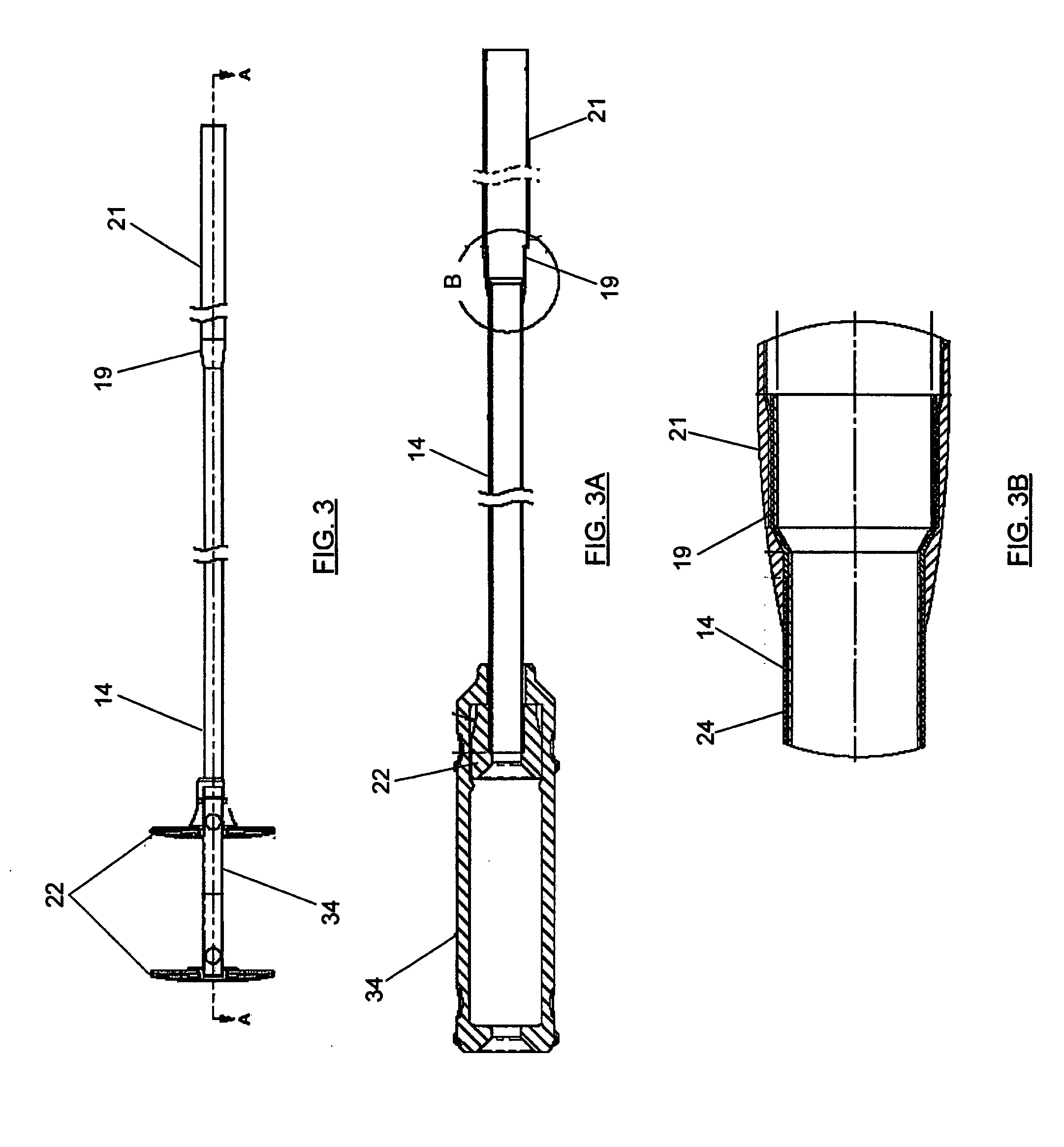
[0031] With reference to FIGS. 1-2A, a delivery device 10 is shown. The delivery device 10 generally includes an inner tube 12 positioned within an outer tube 14 and capable of sliding therein. The delivery device 10 also includes a deployment mechanism 20 that is capable of deploying an implantable device 16 out of the distal end of the outer tube 14 and adjacent to a target area. As will be explained in further detail below, one or more anchors 18 are positioned on the inner tube 12 to stabilize the implantabl...


PUM


Abstract

A delivery device for positioning and deploying an implantable device within a lumen is provided. The device includes an inner tube positioned within an outer tube and capable of sliding therein, wherein the inner and outer tubes have proximal and distal ends. A mechanism is coupled to at least one of the inner and outer tubes and is operable to deploy the implantable device within the lumen. At least one anchor is positioned on the inner tube to stabilize the implantable device by engaging at least a portion of the implantable device while the mechanism deploys the device. The anchor is positioned on the inner tube such that the anchor is freely rotatable about the inner tube.

Description

CROSS-REFERENCE TO RELATED APPLICATIONS [0001] The present application claims priority U.S. Provisional Application No. 60 / 680,678 entitled “Delivery Device with Anchoring Features and Associated Method,” filed May 13, 2005, the contents of which are incorporated herein by reference.BACKGROUND OF THE INVENTION [0002] 1) Field of the Invention [0003] The present invention relates to a delivery device and, in more particular, to a delivery device that employs anchoring features to stabilize an implantable device during deployment of the implantable device within a lumen. [0004] 2) Description of Related Art [0005] Stents are devices that are inserted into body lumina such as vessels or passages to keep the lumen open and prevent closure due to a stricture, external compression, or internal obstruction. In particular, stents are commonly used to keep blood vessels open in the coronary arteries, and they are frequently inserted into the ureters to maintain drainage from the kidneys, the...

Claims


Application Information

Patent Timeline
IPC IPC(8): A61F2/06
CPCA61F2/95A61F2/966A61F2002/9665
Inventor GRIFFIN, MARK ALAN
Owner MERIT MEDICAL SYST INC
Learn More