Deployable bullets

a technology of bullets and bullets, applied in the field of bullets, can solve the problems of significant flaws in the design of all these types of personal security tools, rubber bullets still kill to often and only work, and achieve the effect of reducing the momentum of the bullet and increasing the footprint of the bull

Inactive Publication Date: 2007-05-10
OMNITEK PARTNERS LLC
View PDF21 Cites 8 Cited by
  • Summary
  • Abstract
  • Description
  • Claims
  • Application Information

AI Technical Summary

Benefits of technology

[0009] An objective of the present invention is to provide novel bullets that have deployable blades or other portions thereof to increase the footprint of the bullet and / or decrease the momentum of the bullet.
[0010] The bullets of the present invention are particularly suited for crowd control systems for law enforcement, as non-lethal weapons for law enforcement and military, and as a much more effective and safer replacement for tranquilizer darts used on animals. Although, the methods and devices of the present invention are applicable to bullets, darts, and other gun-fired projectiles, the same will be collectively referred to herein as bullets. These applications are generally much more effective than the systems that they are designed to replace while being also considerably safer. As a preferred implementation, one version of the proposed concept replaces currently used rubber bullets for being significantly safer and more effective.
[0011] Accordingly, a method for non-lethal crowd and personal protection is provided. The method comprising: firing non-lethal bullets towards a person; and deploying portions on the non-lethal bullets prior to impacting the person to decrease its impact pressure on the person.
[0016] Still further provided is a bullet comprising: a shell; deployable portions housed in or integral with the shell; and means for deploying the portions prior to impacting the person to increase the footprint of the projectile.

Problems solved by technology

Rubber type bullets are also used in delicate environments, such as on aircraft, where a regular bullet may compromise the pressurized environment inside the aircraft cabin.
There are significant flaws in the designs of all these types of personal security tools.
Modern day rubber bullets still kill to often and are only effective if they target and impact a person's torso or leg area.
If they impact a person's head, they can do considerable damage and even cause death, which is not generally the intent in situations that call for the use of rubber bullets.
The stun guns and batons must be used at point blank range and are useless unless full contact is made.
Air tasers are limited to 15 feet and can only be fired once.

Method used


Image

  • Deployable bullets
  • Deployable bullets
  • Deployable bullets

Examples


Embodiment Construction

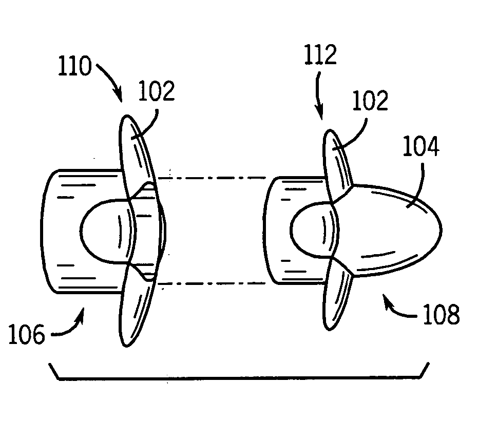
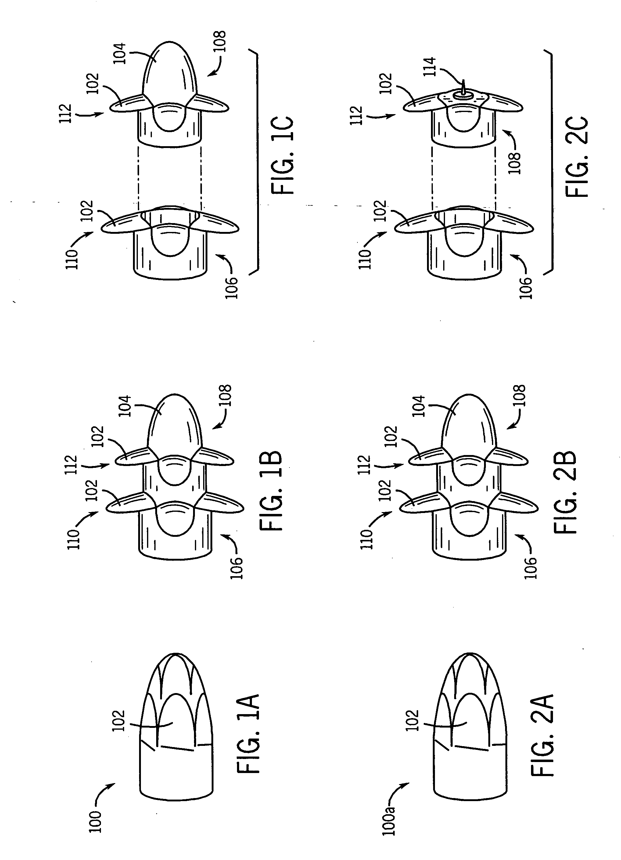
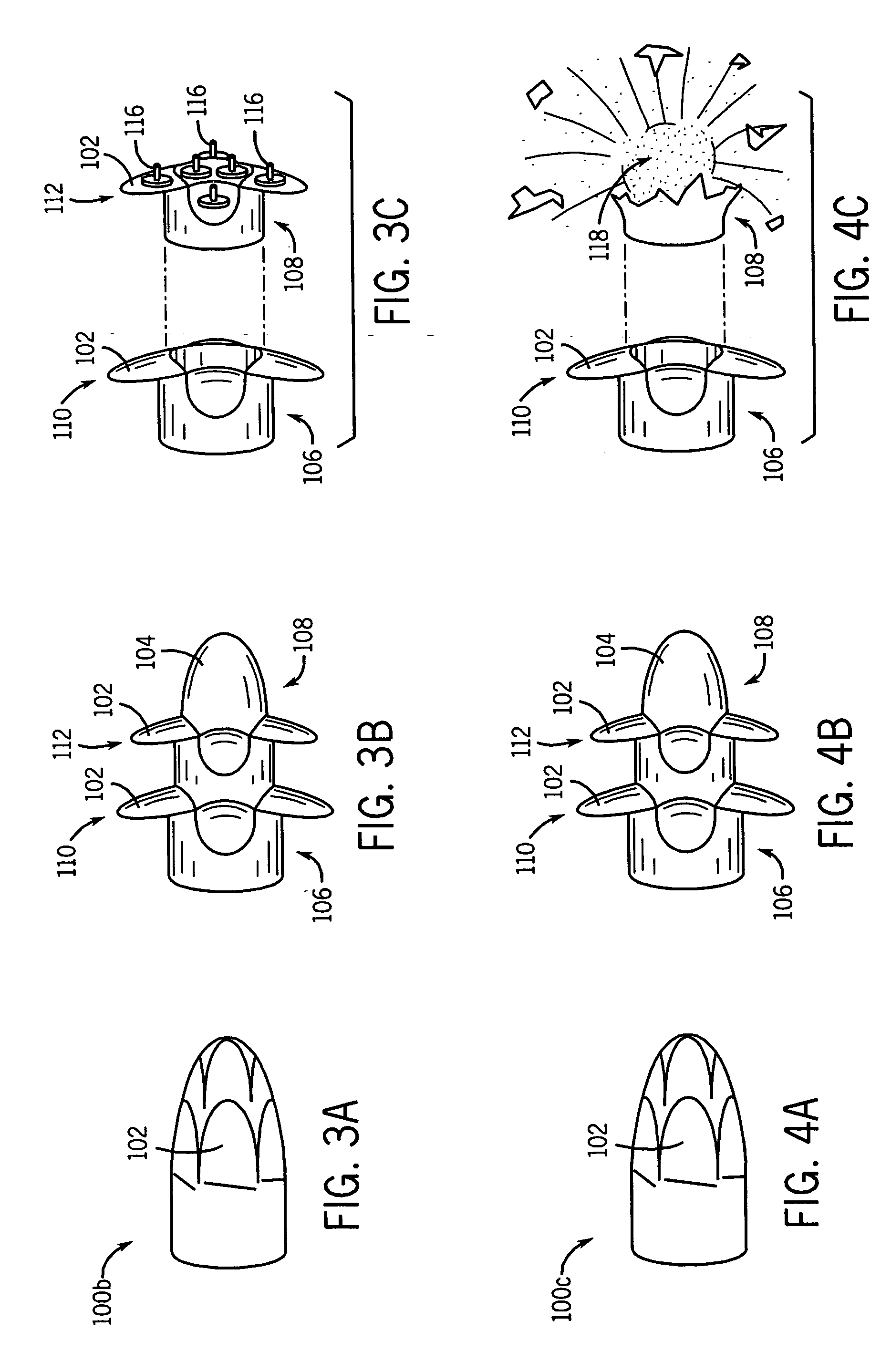
[0030] In operation, a bullet of the present invention is fired from a small or medium caliber gun barrel. The bullet is generally constructed with deployable blades or other deployable portions which act to reduce the momentum of the bullet. As discussed below, the blades or other deployable portion of the bullet can be spring loaded and deployed after exiting the gun barrel. Preferably, the blades or other deployable portion of the bullet are deployed, at least partially, by the centrifugal force on the deployable portion due to the spinning of the bullet when it exits the gun barrel. In both preferred implementations, as discussed below, the blades or other deployable portion can have a weakened portion acting as a living hinge to aid in the deployment of the blades or other deployable portion. Furthermore, due to the airflow around the bullet, once the blades or other deployable portion begins to deploy, the airflow against the same will also aid in their deployment.

[0031] At a...


PUM

PropertyMeasurementUnit
distanceaaaaaaaaaa
distancesaaaaaaaaaa
impact pressureaaaaaaaaaa

Abstract

A method for non-lethal crowd and personal protection. The method includes: firing non-lethal bullets towards a person; and deploying portions on the non-lethal bullets prior to impacting the person to decrease its impact pressure on the person.

Description

CROSS-REFERENCE TO RELATED APPLICATION [0001] This application claims priority to earlier filed U.S. provisional application Ser. No. 60 / 317,308 filed on Sep. 5, 2001, the entire contents of which is incorporated herein by its reference.BACKGROUND OF THE INVENTION [0002] 1. Field of the Invention [0003] The present invention relates generally to bullets, and more particularly, to bullets, which have deployable blades or other portions thereof to increase the footprint of the bullet and / or decrease the momentum of the bullet. [0004] 2. Prior Art [0005] The first less-than-lethal bullets appeared in the 1880s when Singapore police shot sawed-off broom handles at rioters. By the 1960s, riot control police in Singapore, Malaysia, and Hong Kong were using more sophisticated wooden bullets. British colonists brought the idea back home to England, where they replaced the wood—which could shatter and possibly penetrate—with rubber. By the 1980s the British had switched to more accurate plas...

Claims


Application Information

Patent Timeline
Patent Type & Authority Applications(United States)
IPC IPC(8): F42B14/06F41J2/00F42B10/14F42B12/34F42B12/46H01M2/02H01M2/10H01M10/40H01M12/06
CPCF41J2/00F42B10/14F42B12/34F42B12/46
Inventor RASTEGAR, JAHANGIR S.
Owner OMNITEK PARTNERS LLC
Why Eureka
Try Eureka