Substrate treating apparatus

Active Publication Date: 2009-01-01
SOKUDO CO LTD
View PDF118 Cites 36 Cited by
  • Summary
  • Abstract
  • Description
  • Claims
  • Application Information

AI Technical Summary

Benefits of technology

[0048]According to the embodiment defined in (8) a

Problems solved by technology

However, there is not much room for reducing the number of transporting steps for the single main transport mechanism or shortening the time for each transporting step.
Hence, it is difficult to achieve a further improvement in throughput of each block.
It is ther

Method used


Image

  • Substrate treating apparatus
  • Substrate treating apparatus
  • Substrate treating apparatus

Examples


Example

[0063]Embodiments of this invention will be described in detail hereinafter with reference to the drawings.

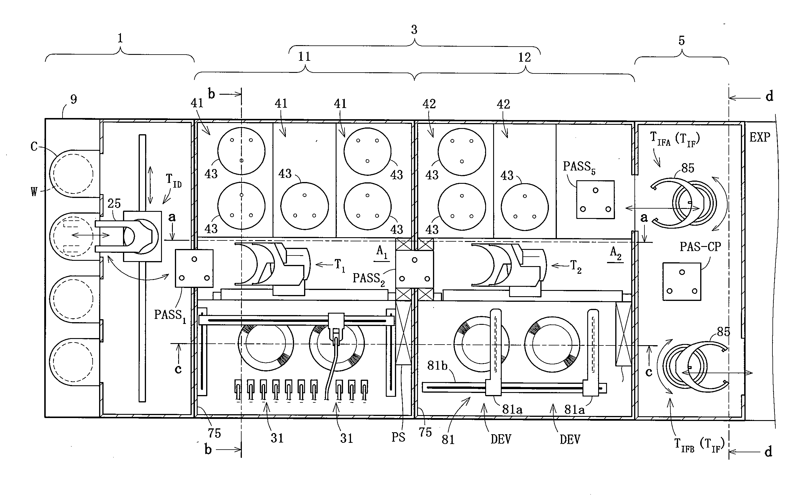
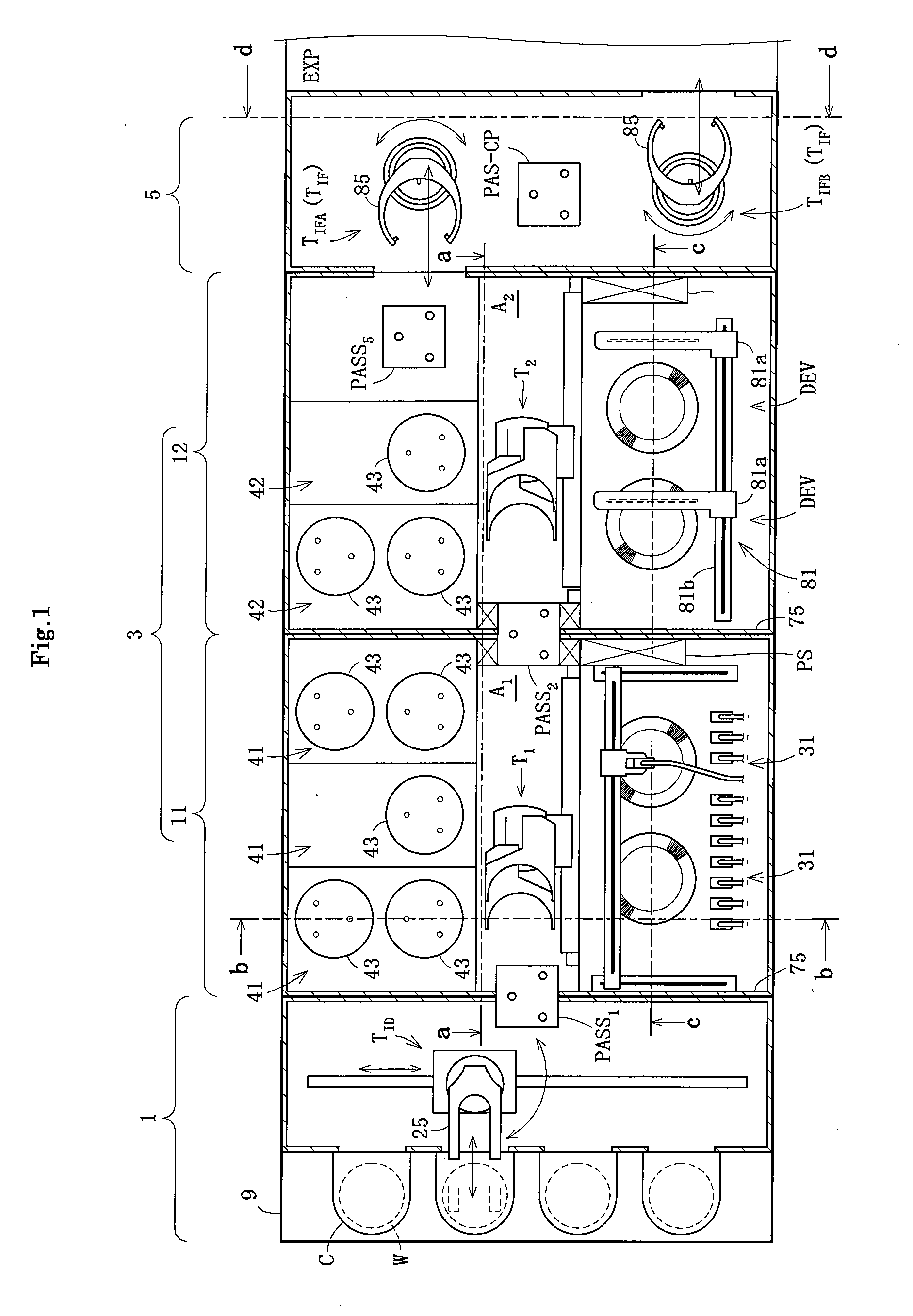
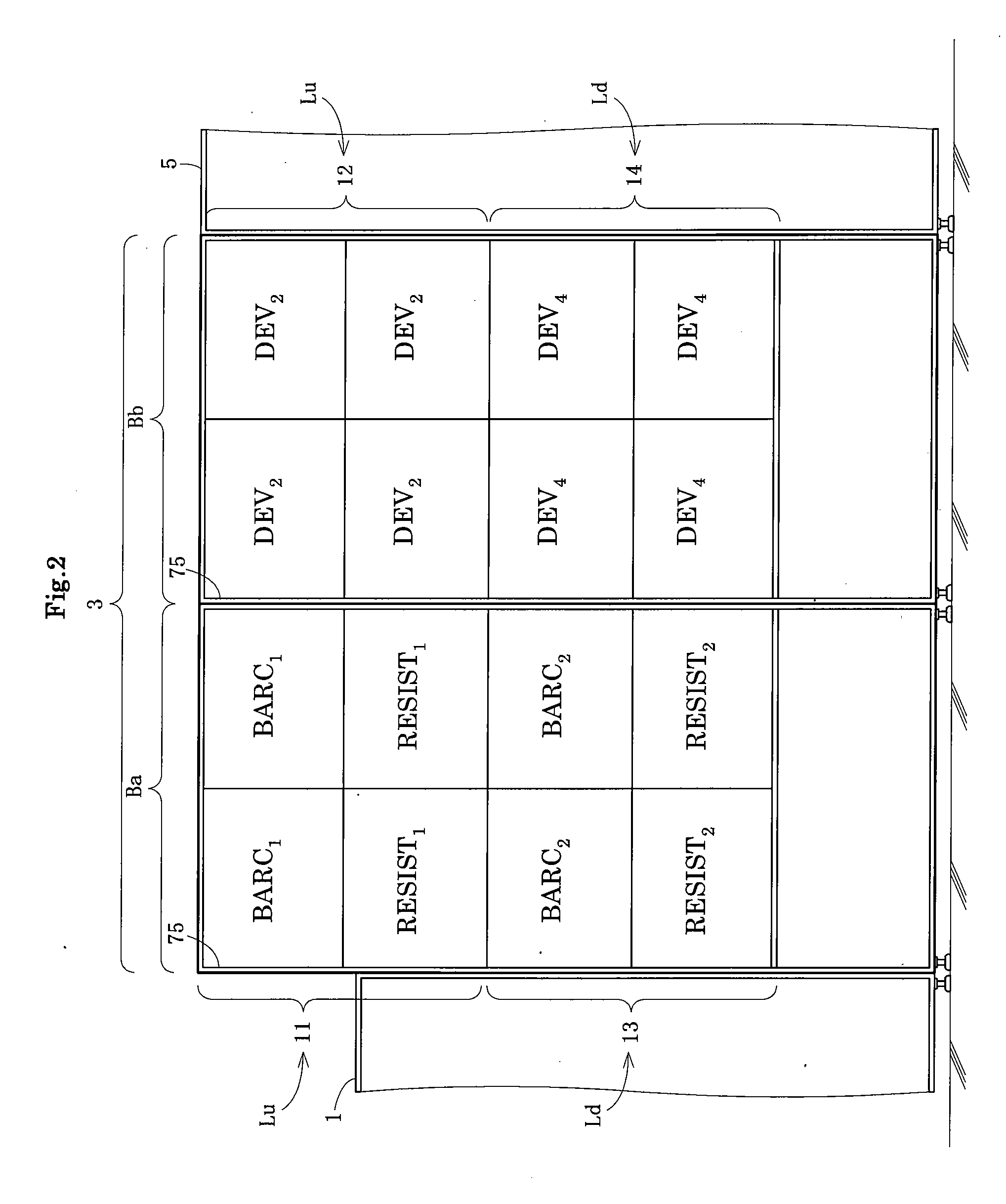
[0064]FIG. 1 is a plan view showing an outline of a substrate treating apparatus according to an embodiment of the present invention. FIGS. 2 and 3 are schematic side views showing an arrangement of treating units included in the substrate treating apparatus. FIGS. 4 through 7 are views in vertical section taken on lines a-a, b-b, c-c and d-d of FIG. 1, respectively.

[0065]This embodiment provides a substrate treating apparatus for forming resist film on substrates (e.g. semiconductor wafers) W, and developing exposed wafers or substrates W. This apparatus is divided into an indexer section (hereinafter called “ID section”) 1, a treating section 3, and an interface section (hereinafter called “IF section”) 5. The ID section 1 and IF section 5 are arranged adjacent to and on the opposite sides of the treating section 3. An exposing machine EXP which is an external apparatus separ...


PUM

PropertyMeasurementUnit
Heightaaaaaaaaaa
Transport propertiesaaaaaaaaaa

Abstract

A substrate treating apparatus includes a plurality of substrate treatment lines arranged vertically. Each substrate treatment line has a plurality of main transport mechanisms arranged horizontally, and a plurality of treating units provided for each main transport mechanism for treating substrates. A series of treatments is carried out for the substrates, with each main transport mechanism transporting the substrates to the treating units associated therewith, and transferring the substrates to the other main transport mechanism horizontally adjacent thereto. The substrate treating apparatus realizes increased processing capabilities by treating the substrates in parallel through the substrate treatment lines.

Description

CROSS-REFERENCES TO RELATED APPLICATIONS[0001]This application claims priority to Japanese Patent Application No. 2007-172496, filed Jun. 29, 2007. The disclosure of Japanese Patent Application No. 2007-172496 is hereby incorporated by reference in its entirety for all purposes.BACKGROUND OF THE INVENTION[0002](1) Field of the Invention[0003]This invention relates to a substrate treating apparatus for performing a series of treatments of substrates such as semiconductor wafers, glass substrates for liquid crystal displays, glass substrates for photomasks, and substrates for optical disks (hereinafter called simply “substrates”).[0004](2) Description of the Related Art[0005]Conventionally, a substrate treating apparatus is used to form a resist film on substrates, allows the substrates having the resist film formed thereon to be exposed in a separate exposing machine, and develops the exposed substrates. Specifically, the substrate treating apparatus includes a plurality of blocks ea...

Claims


Application Information

Patent Timeline
IPC IPC(8): B05C11/00B05C13/00
CPCH01L21/6715H01L21/67173H01L21/67178H01L21/67017Y10S414/135B05B15/1248H01L21/67184B05D3/0486B05C13/00H01L2924/0002H01L2924/00B05B14/43G03F7/16H01L21/0274H01L21/682H01L21/67196H01L21/67201H01L23/34H01L21/67225B05B14/44H01L21/02623H01L21/6719H01L21/67739B05B14/30H01L21/67207H01L21/67742Y10S118/07H01L21/67161F24F3/167B05C13/02G03F7/26
Inventor FUKUTOMI, YOSHITERUMITSUHASHI, TSUYOSHIOGURA, HIROYUKIMORINISHI, KENYAKAWAMATSU, YASUONAGASHIMA, HIROMICHI
Owner SOKUDO CO LTD
Why Eureka
Try Eureka