Projection system utilizing fiber optic illumination

Inactive Publication Date: 2006-03-21
HONEYWELL INT INC
View PDF5 Cites 13 Cited by
  • Summary
  • Abstract
  • Description
  • Claims
  • Application Information

AI Technical Summary

Benefits of technology

[0031]In one embodiment, a projection-based tiled display system, a single frame-sequential imager is used for each projection element, with centrally orchestrated electronic color switching, thereby eliminating the need to associate color separation and recombination optics with each imager, maintaining color balance between projectors, and greatly simplifying the construction within each projector. Plastic optical fibers (POFs) are employed to minimize cost and unique non-imaging optics are used to eliminate packing fraction losses. Such POFs are generally referred to as solid core and large core. Small core POFs are available from Mitsubishi, under the ESKA™ brand, with fibers up to ˜3 mm core diameter. Large core POF, up to ˜18 mm core diameter, are manufactured by Lumenyte under the Sta-Flex® brand, as well as OptiCore™ by Fiberstars, and Light Fiber from Sumitomo 3M. It is anticipated that technology being promoted for communications grade POFs wi

Problems solved by technology

A unitary projector or direct-view display cannot meet size and resolution requirements.
To effect seamless operation, any perceived border between tiles must be eliminated, thereby adding additional complexity, especially when the pixel pitch at the viewing surface is less than a few millimeters.
Both projection- and direct-view tiling systems have the following cost disadvantages when compared with a unitary display.1. The need for additional components, such as optical masks and feedback systems, that need to be inserted to hide the seams.2. Niche-market status, leading to high recurring cost since the investment for lower cost solutions does not have adequate payback time.3. Labor hours to accurately align tiles and calibrate the system during assembly.
Both projection- and direct-view tiling systems have the following performance disadvantages when compared with a unitary display.1. Non-uniformities between tiled elements induced by minor differences between components in one or more of the tiles.
Projection-based tiled systems have the following cost disadvantages when compared with systems that employ a unitary projector.1. Concentrated heat load in the volume around the projector array, necessitating special room-cooling considerations2. Concentrated fan-noise in the volume around the projector array, necessitating special sound-dampening considerations3. Maintenance costs involved in replacing lamps suspended near the ceiling, especially for the projectors in the middle of the array that may be hard to access4. Need for a feedback control system to ensure alignment between tiled elements5. Higher a

Method used


Image

  • Projection system utilizing fiber optic illumination
  • Projection system utilizing fiber optic illumination
  • Projection system utilizing fiber optic illumination

Examples


Example

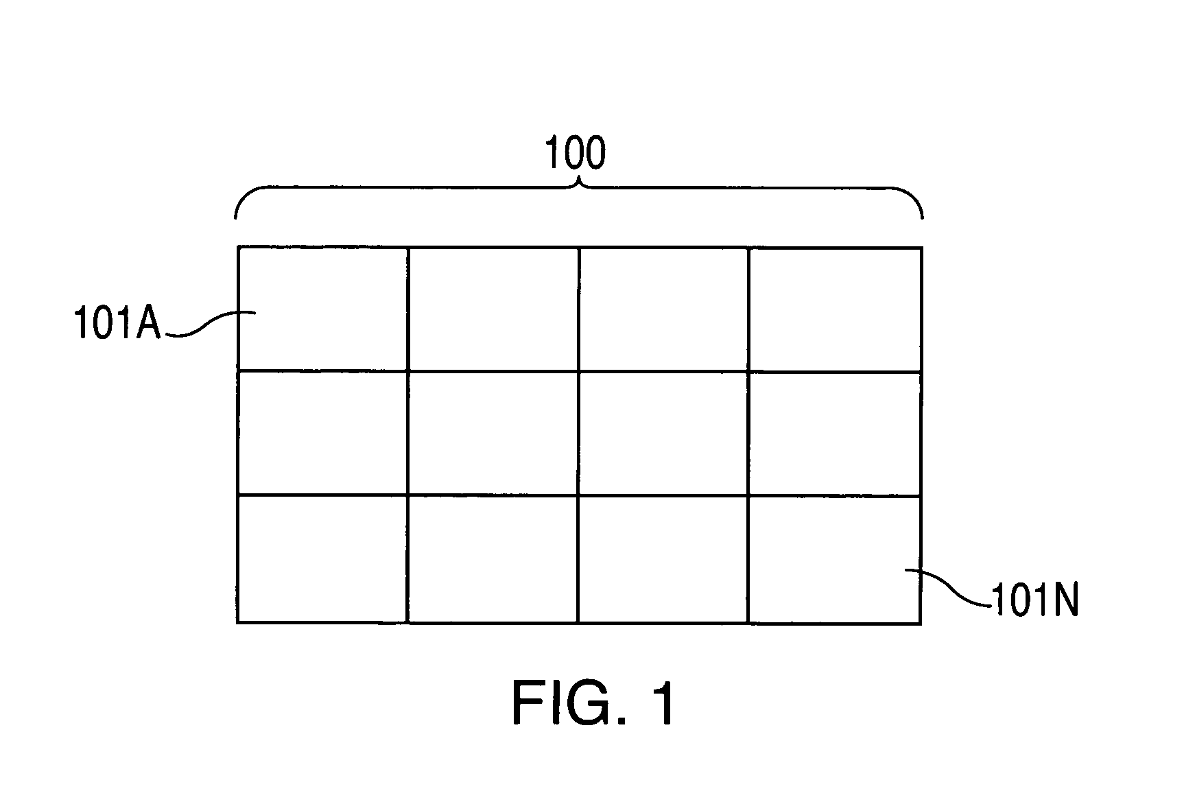
[0057]Referring first to FIG. 1, a tiled projected image 100 is composed of individual display tiles 101A . . . 101N. A preferred embodiment of my invention has a three-row by four-column array of display tiles as shown in FIG. 1. Further embodiments contemplated can have different tile configurations including non-rectangular display tiles, such as hexagons, and tile configurations where the composite projected display is non-rectangular, such as a triangle, or non-planar, such as a hemisphere.

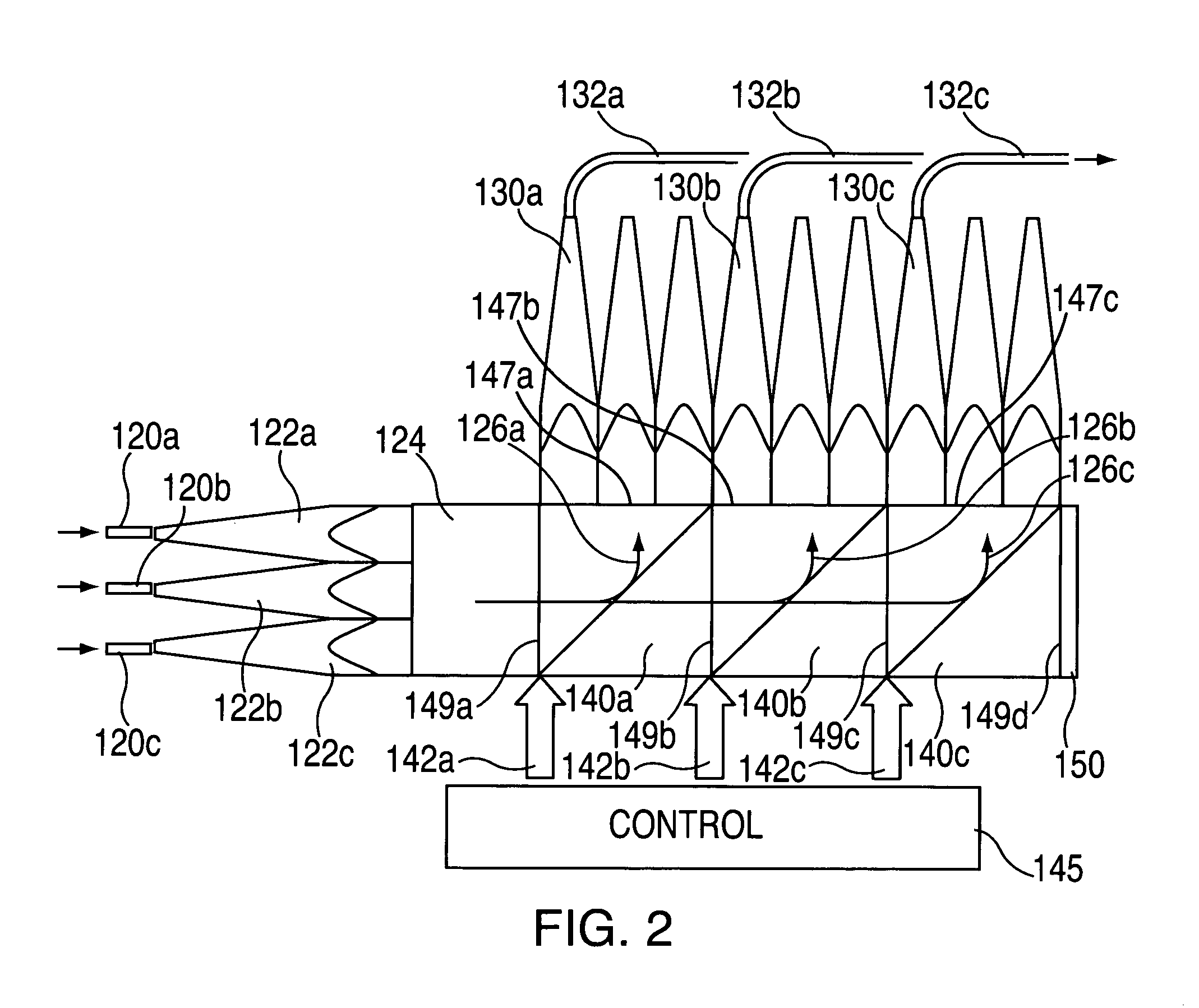
[0058]Referring to FIG. 2, an array of fibers 120a, b, c provide a source of white light into an array of non-imaging morphing collimating elements (NIMCOLEs) 122a, b, c respectively. Each NIMCOLE interfaces with a round fiber, and then collimates the received energy from the fiber with a conical tapered feature, and then morphs the output from a round cross section to one of polygonal cross section (in this example, square). The polygonal cross section remains constant for a distance, provid...


PUM


Abstract

An optical illumination, communication, or beam splitting system includes close-packed non-imaging morphing optical elements, beam splitting prisms, output elements, including non-imaging concentrating elements and optical detectors, and a beam dump for receiving energy from the beams not directed to the output elements, in various combinations. The sources of electromagnetic energy may comprise semiconductors emitting at different bands of wavelengths, wherein each band comprises a different color.

Description

[0001]This application claims the benefit of Provisional Application No. 60 / 300,999, filed Jun. 26, 2001.BACKGROUND OF THE INVENTION[0002]1. Technical Field[0003]This invention is directed to a method and apparatus for illuminating electro-optical devices, a more specifically to projection system that uses optical fibers to distribute light.[0004]2. Background Art[0005]By far the most popular large-screen device is the projection display. Historically the source of the image was a cathode ray tube, and recently there has been great strides made with microdisplay imagers, both transmissive and reflective. Recently, JVC introduced a state-of-the-art liquid crystal on silicon (LCOS) imager, 1.3″ diagonal device with 1920×1080 pixels. For resolutions higher than this, a tiled system would be employed. For example, Olympus Optical Co. has developed a tiled projection system using nine projectors, each 600×800 in a 3×3 matrix to create a 100″ diagonal display with 2400×1800 pixels, with a...

Claims


Application Information

Patent Timeline
IPC IPC(8): H04N5/66H04N5/74G02B6/28G02B6/34G02B27/14H04N9/12H04N9/31
CPCG02B27/1046G02B27/145G02B27/149H04N9/3197H04N9/12H04N9/3164H04N9/3167H04N5/74G02B6/2817H04N9/3147
Inventor SACCOMANNO, ROBERT J.
Owner HONEYWELL INT INC
Why Eureka
Try Eureka