
Respiratory mask

Inactive Publication Date: 2007-05-10
SLEEPNET
View PDF6 Cites 10 Cited by
  • Summary
  • Abstract
  • Description
  • Claims
  • Application Information

AI Technical Summary

Benefits of technology

[0008] The present invention relates to a respiratory mask that is more comfortable to wear and conforms better to a wearer's face. It is a system for stiffening one or more portions of a formable element disposed around the perimeter of the respiratory mask.

Problems solved by technology

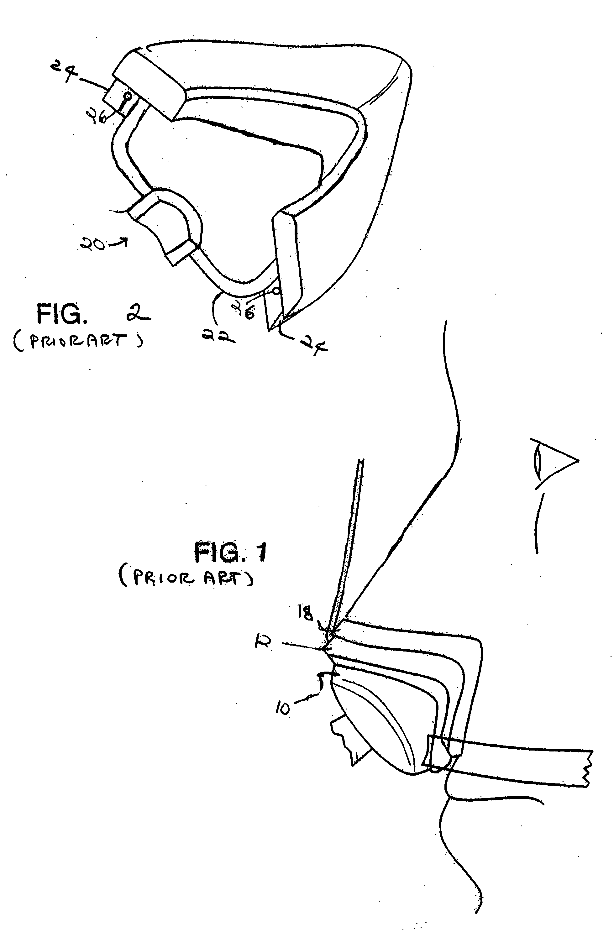
Thus, during extended use, the mask may move relative to the patient's nose or face breaking the gas tight seal or becoming uncomfortable.
The customary response is for the patient to tighten the mask's straps, which may cause the mask to push too strongly on the soft tissue surrounding the patient's nose or on the patient's face.
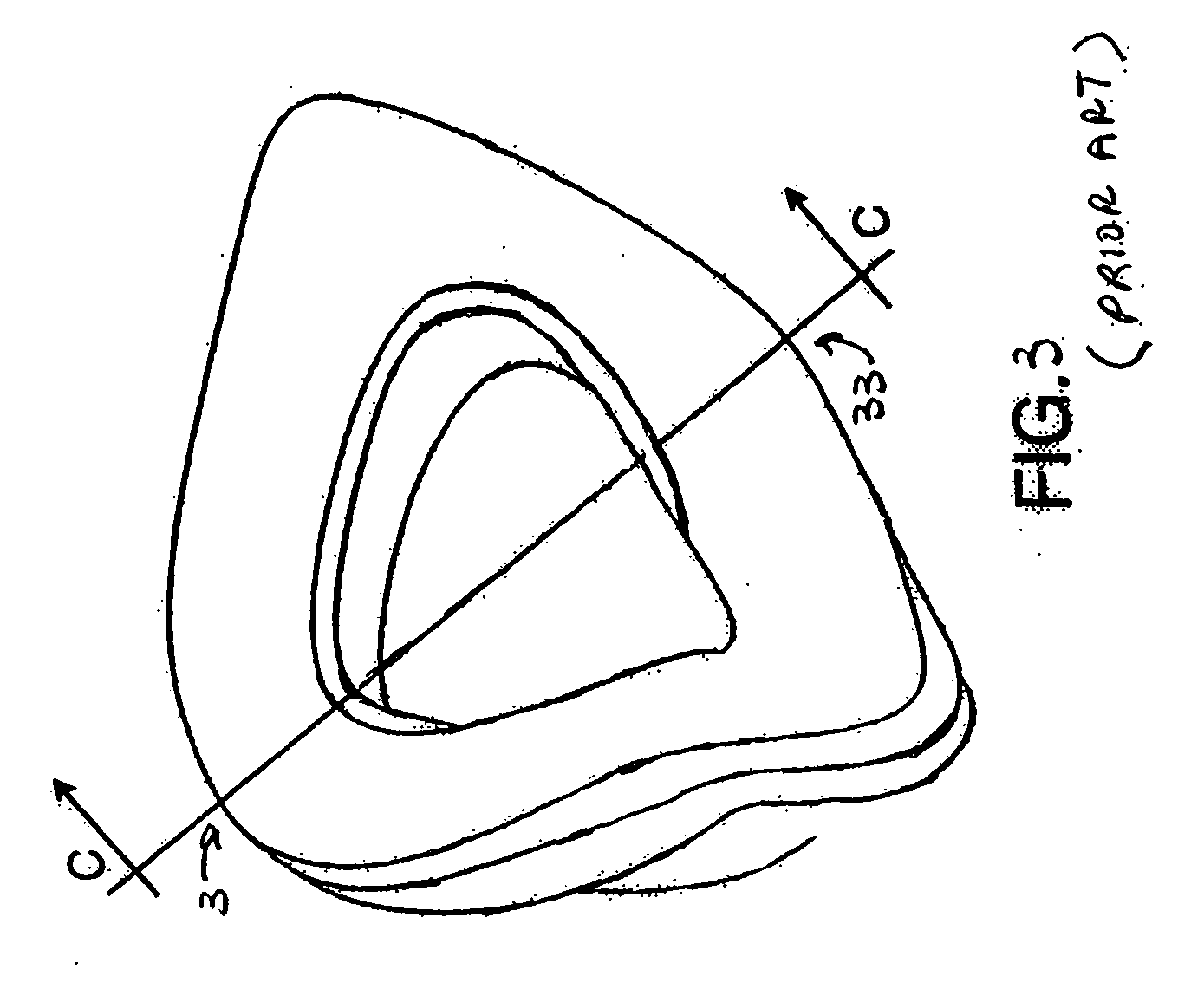
This crease causes the mask to become uncomfortable and causes the gas tight seal to be broken.

Method used


Image

  • Respiratory mask
  • Respiratory mask
  • Respiratory mask

Examples


Embodiment Construction

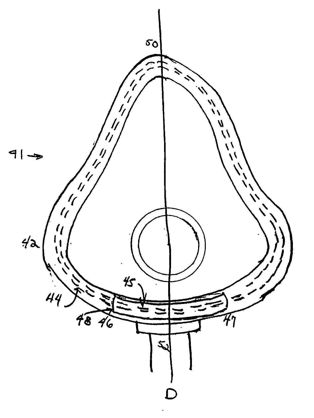
[0014] The present invention provides a system for stiffening, as described in more detail herein, a portion of the perimeter of a mask that has a formable element disposed about its perimeter. Referring to FIG. 4, one preferred embodiment of a full face mask 41 has a shell 42 constructed of a compliant and resilient material. A formable element 44 is disposed along the perimeter, and only the perimeter, of the shell 42. The formable element 44 can be affixed to the surface of the shell 42 but is molded within the shell 42 here. A portion 45 of the formable element 44 running along the wearer's chin from 46 to 47 is stiffened. It is stiffened in this preferred embodiment by molding a polycarbonate sleeve 48 over the portion 45 of the formable element 44 before the formable element 44, and polycarbonate sleeve 48, are molded in the shell 42. This causes the portion 45 of the formable element 44 to become more difficult to bend but not to be rigid, i.e., to be stiffened, compared to t...


PUM


Abstract

The present invention is a system for stiffening a portion of the perimeter of a respiratory mask that has a formable element disposed about its perimeter, thereby making the respiratory mask more comfortable to wear.

Description

CROSS-REFERENCE TO RELATED APPLICATIONS [0001] The present application claims the benefit of provisional application Ser. No. 60 / 741,304 filed Dec. 1, 2005, which is incorporated here by reference, and is a continuation in part of patent application Ser. No. 09 / 979,972 filed Nov. 28, 2001.TECHNICAL FIELD [0002] This invention relates to a respiratory mask used to supply a breathable gas to a patient. More specifically, it relates to a better means to conform such a mask, whether it is a nasal or full-face respiratory mask (hereinafter, collectively, “masks”), to the portions of a patient's face that the mask contacts. BACKGROUND OF THE INVENTION [0003] A number of relatively common breathing disorders are treated by delivery of pressurized, breathable gas to a patient's airway. This is customarily done through the use of a mask. A mask is normally held in place over a patient's nose or face by one or more straps. The straps encircle the patient's head and are adjusted to create a ga...

Claims


Application Information

Patent Timeline
IPC IPC(8): A62B18/02
CPCA61M16/06A61M16/0605A62B18/02
Inventor CHIESA, PAULPARK, DOUG
Owner SLEEPNET
Learn More