

Optimal imaging system and method for a stencil printer
a stencil printer and imaging system technology, applied in the direction of instruments, soldering apparatus, welding devices, etc., can solve the problems of requiring a longer integration time to achieve proper exposure, requiring two cameras, and consuming a lot of time for the sequence imaging of the area of the circuit board,
- Summary
- Abstract
- Description
- Claims
- Application Information
AI Technical Summary
Benefits of technology
Problems solved by technology
Method used
Image

Examples
Embodiment Construction
[0032] For purposes of illustration, embodiments of the present invention will now be described with reference to a stencil printer used to print solder paste onto a circuit board. One skilled in the art will appreciate that embodiments of the present invention are not limited to stencil printers that print solder paste onto circuit boards, but rather, may be used in other applications requiring dispensing of other viscous materials, such as glues, encapsulents, underfills, and other assembly materials suitable for attaching electronic components onto a circuit board. Thus, any reference to solder paste herein contemplates use of such other materials. Also, the terms “screen” and “stencil” may be used interchangeably herein to describe a device in a printer that defines a pattern to be printed onto a substrate.
[0033]FIG. 5 shows a front perspective view of a stencil printer, generally indicated at 30, in accordance with one embodiment of the present invention. The stencil printer 3...
PUM
| Property | Measurement | Unit |
|---|---|---|
| Area | aaaaa | aaaaa |
| Distance | aaaaa | aaaaa |
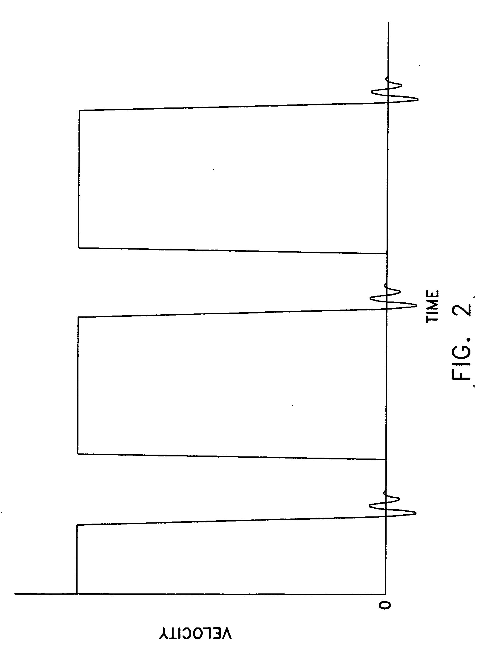
| Velocity | aaaaa | aaaaa |
Abstract
Description
Claims
Application Information