
Display device and projector

a technology which is applied in the field of projection device and projector, can solve the problems of difficult to apply the above technique to a projection device that requires such a light source, difficult to correctly guide the light, and irradiate the light, so as to reduce the number of parts, facilitate the utilization of light, and reduce the slowness of dynamic images

Inactive Publication Date: 2007-05-10
SEIKO EPSON CORP
View PDF30 Cites 14 Cited by
  • Summary
  • Abstract
  • Description
  • Claims
  • Application Information

AI Technical Summary

Benefits of technology

[0010] Accordingly, the present invention provides a display device and a projector capable of enhancing the image quality of dynamic images, reducing limitations on light sources, enhancing the utilization efficiency of light, and displaying images in full color.
[0039] Furthermore, in an aspect of the present invention, the distances from the light sources to the optical parts are almost the same for each colored light component in the projector where illumination light is divided into two or more colored light components. Therefore, it is possible to realize a structure in which the respective colored light components are correctly irradiated onto the display elements when the illumination region are the same size and the scanning directions of the respective colored light components are the same. As a result, it is possible to enhance the quality of dynamic images and the utilization efficiency of light and to display images in full color. Also, it is possible to share optical parts, and thereby reduce the number of parts by making the distances from the light sources to the optical parts almost the same for each colored light component in a projector where illumination light is divided into two or more colored light components.

Problems solved by technology

However, it is difficult to apply the above technique to a display device that requires such a light source.
However, since light diffused and emitted from the light sources to various directions is limited to one direction by rotating a condensing barrel in which a slit is formed, it is difficult to correctly guide the light that does not directly pass through the slit to a display element and thereby to irradiate the light.
Since a region to be illuminated is scanned by scanning a member for shielding light, it is difficult to enhance the utilization efficiency of light by the amount of light that reaches the member for shielding light.
Therefore, it is not possible to scan the illumination light to the display element while maintaining a uniform incidence angle of illumination light.
Since it is not possible to illuminate the entire region to be illuminated in the same state, it is difficult to display images with uniform image quality.

Method used


Image

  • Display device and projector
  • Display device and projector
  • Display device and projector

Examples


first exemplary embodiment

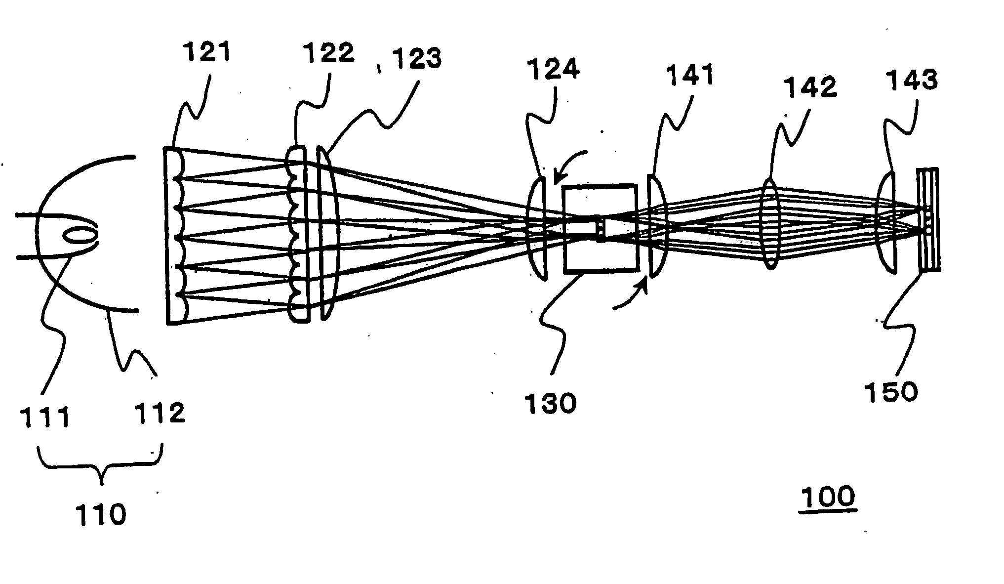
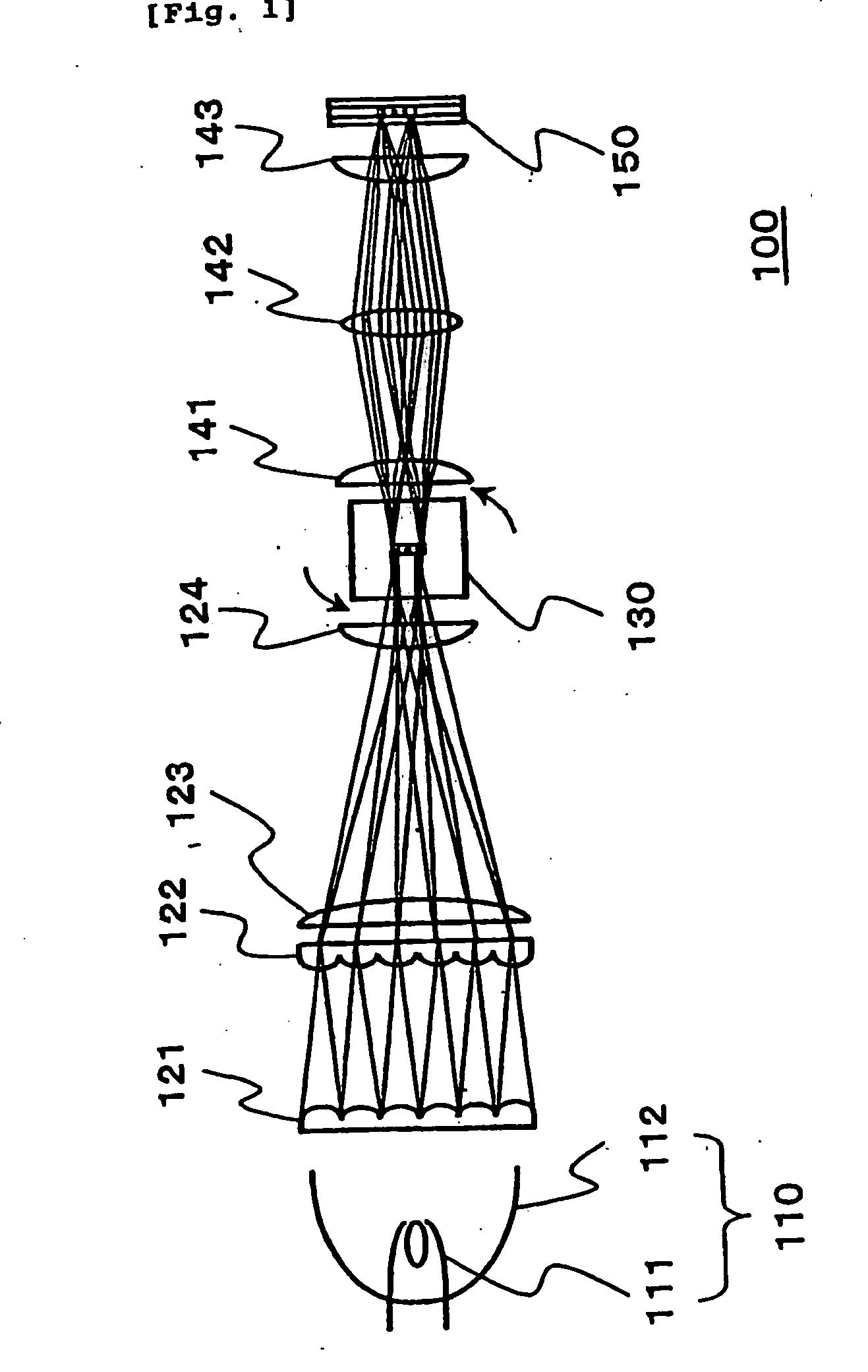
[0054]FIG. 1 illustrates a display device according to the first exemplary embodiment of the present invention. A display device 100 includes a light source lamp 110 (a light source), fly eye lenses 121 and 122, a superposing lens 123, a collimating lens 124 (image forming device), a rotating prism 130 (illumination light scanning device), image re-forming lenses 141, 142, and 143 (image re-forming means), and a liquid crystal light valve 150 (a display element).

[0055] The respective parts will be described in detail. The light source lamp 110 includes a lamp 111 that serves as a light source and a concave mirror 112. The lamp 111 includes, for example, a discharge lamp, such as a high-pressure mercury lamp. Further, the concave mirror 112 includes a parabolic mirror. Moreover, the structures of the lamp 111 and the concave mirror 112 are not limited thereto and can be appropriately modified. Furthermore, it is not necessary to intermittently turn on and off the lamps that serve as...

second exemplary embodiment

[0077] According to the present exemplary embodiment described hereinafter, the same members as those of the above-mentioned exemplary embodiment are denoted by the same reference numerals and the description of the same operations is omitted. In cases where members have the same name, although they are denoted by different reference numerals, they have almost the same function. Therefore, the basic description thereof is omitted.

[0078]FIG. 5 illustrates a projector according to the second exemplary embodiment of the present invention. A projector 201 includes a light source lamp 110, fly eye lenses 121 and 122, a superposing lens 123, a collimating lens 124, a rotating prism 130, a color dividing dichroic prism 271, reflecting mirrors 281R, 282R, 281B, and 282B, image re-forming lenses 241R, 242R, 243R, 241G, 242G, 243G, 241B, 242B, and 243B, liquid crystal light valves 250R, 250G, and 250B, a color synthesizing dichroic prism 272, and a projection lens 260.

[0079] For the simplic...

third exemplary embodiment

[0091] According to the present exemplary embodiment described hereinafter, the same members as those of the above-mentioned exemplary embodiments are denoted by the same reference numerals and the description of the same operations is omitted. In cases where members have the same name, although they are denoted by different reference numerals, they have almost the same function. Therefore, the basic description thereof is omitted.

[0092]FIG. 6 is a perspective view of a projector according to the third exemplary embodiment of the present invention. The projector 301 includes a light source lamp 110, fly eye lenses 121 and 122, a superposing lens 123, a collimating lens 124, a rotating prism 130, a color dividing dichroic prism 271, reflecting mirrors 381R, 382R, 381G, 382G, 381B, and 382B, image re-forming lenses 341, 342R, 343R, 342G, 343G, 342B, and 343B, liquid crystal light valves 250R, 250G, and 250B, a color synthesizing dichroic prism 272, and a projection lens 260.

[0093] T...


PUM

PropertyMeasurementUnit
aspect ratioaaaaaaaaaa
rotationaaaaaaaaaa
aspect ratioaaaaaaaaaa

Abstract

To provide a display device and a projector capable of enhancing the quality of dynamic images, of reducing limitations on light sources, enhancing the utilization efficiency of light, and of displaying images in full color, illumination light emitted from a light source lamp is irradiated onto some pixels of a liquid crystal light valve capable of displaying images in colors. A rotating prism scans the illumination light. At this time, fly eye lenses and an superposing lens condense illumination light emitted from the light source lamp to form an image. The image formed by the fly eye lenses and the superposing lens is formed again on the liquid crystal light valve by the image re-forming lenses. The image of the liquid crystal light valve is enlarged and projected by the projection lens to a screen.

Description

[0001] This is a Continuation of application Ser. No. 10 / 762,352 filed Jan. 23, 2004. The disclosure of the prior application is hereby incorporated by reference herein in its entirety.BACKGROUND OF THE INVENTION [0002] 1. Field of Invention [0003] The present invention relates to a display device to irradiate illumination light emitted from a light source onto display elements, thereby displaying images, and to a projector to make illumination light that is modulated by a plurality of pixels incident on a projection lens of the display element and projecting images from the projection lens to a screen, thereby displaying the images. [0004] 2. Description of Related Art [0005] In related art display devices, a technique is known wherein the image quality of dynamic images is enhanced by scanning a region onto which the illumination light is irradiated to a display device. [0006] In a related art display element, a structure is known wherein a region onto which illumination light is ...

Claims


Application Information

Patent Timeline
Patent Type & Authority Applications(United States)
IPC IPC(8): G03B21/28G03B21/00G02F1/13G03B21/14G03B21/20H04N9/31
CPCH04N9/3197H04N9/3117G02B27/283G03B21/208
Inventor KOJIMA, HIDEKI
Owner SEIKO EPSON CORP
Learn More