
Apparatus and methods for remote viewing and scanning of microfilm

Inactive Publication Date: 2007-05-10
DIGITAL CHECK CORP
View PDF29 Cites 21 Cited by
  • Summary
  • Abstract
  • Description
  • Claims
  • Application Information

AI Technical Summary

Benefits of technology

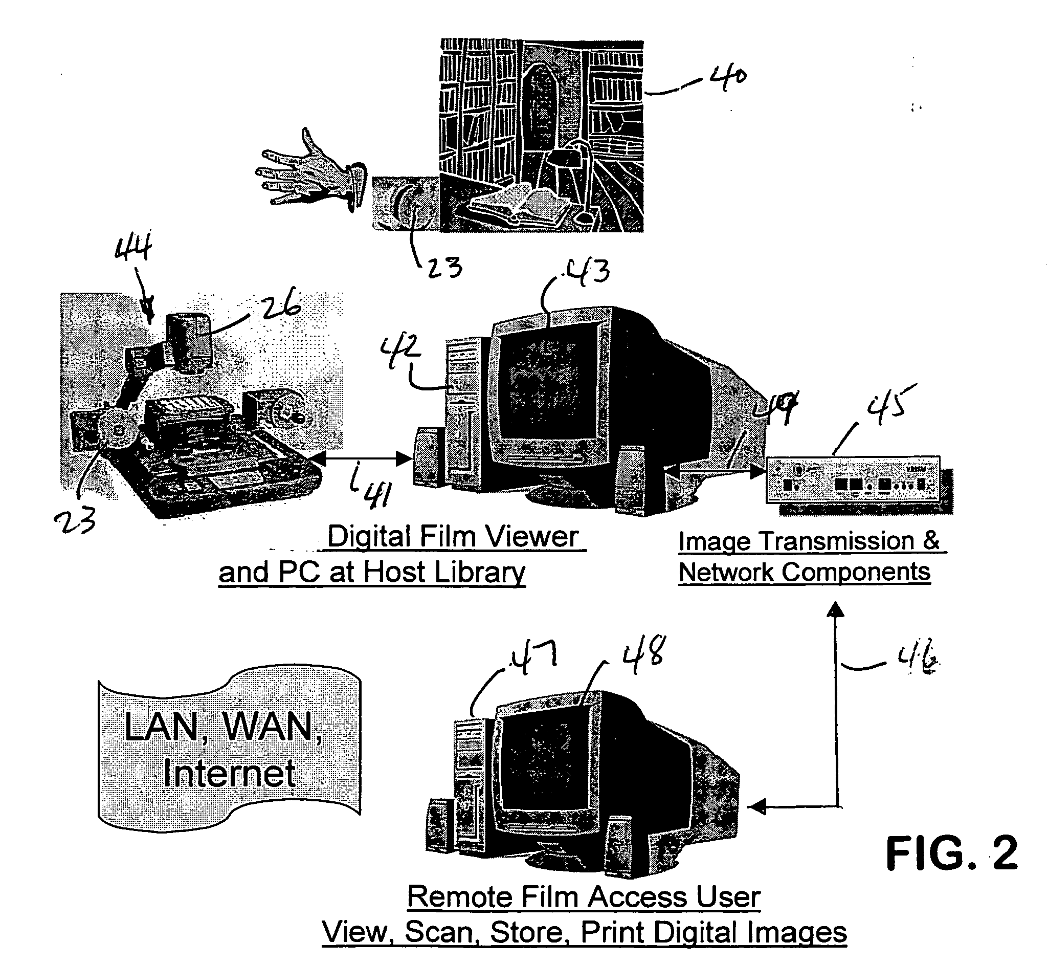
[0015] The present invention also includes related methods performed by the above apparatus. One method of scanning microfilm at a first location while viewing and controlling the scanning from a remote location includes the steps of generating a video image of the microfilm at the first location, communicating the video image from the first location to the remote location, and providing a virtual film movement control at the remote location to enable a user at the remote location to control the movement of the microfilm at the first location. The step of providing a virtual film movement control includes one or more of the sub steps of forward film movement, fast forward film movement, reverse film movement, fast reverse film movement, and stop film movement.
[0016] Another method includes the step of providing a virtual camera control at the remote location for controlling a camera at the first location that generates the images. The step of providing a virtual camera control includes one or

Problems solved by technology

In addition to the distances between the microfilm and the viewers, copyright issues may exist.
The cost of duplicating any microfilm collection may also be prohibitive or impractical due to the millions of images that may exist on hundreds or thousands of rolls of film or microfiche cards.
Many of the same factors also make digitization of microfilm collections impractical and unduly expensive.

Method used


Image

  • Apparatus and methods for remote viewing and scanning of microfilm
  • Apparatus and methods for remote viewing and scanning of microfilm
  • Apparatus and methods for remote viewing and scanning of microfilm

Examples


Embodiment Construction

[0031] It will be understood that the invention may be embodied in other specific forms without departing from the spirit thereof. The present examples and embodiments, therefore, are to be considered in all respects as illustrative and not restrictive, and the invention is not to be limited to the details given herein.

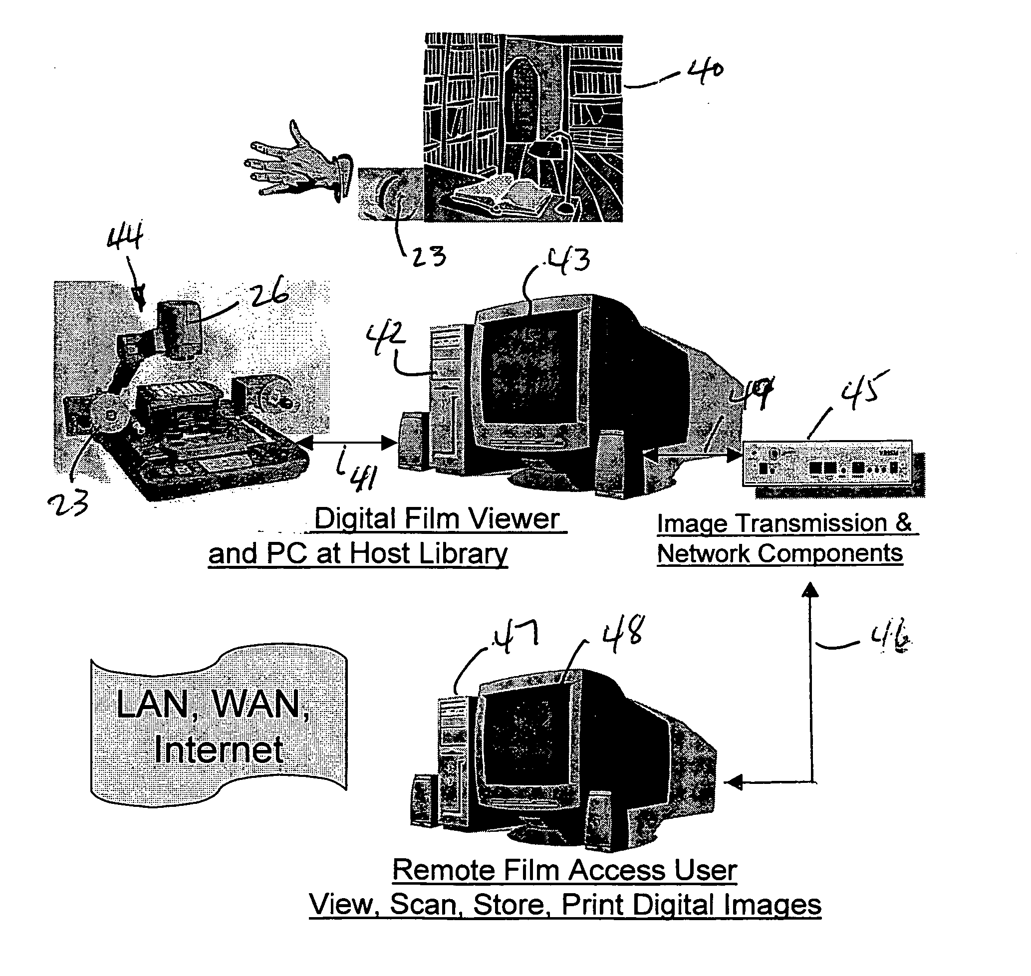
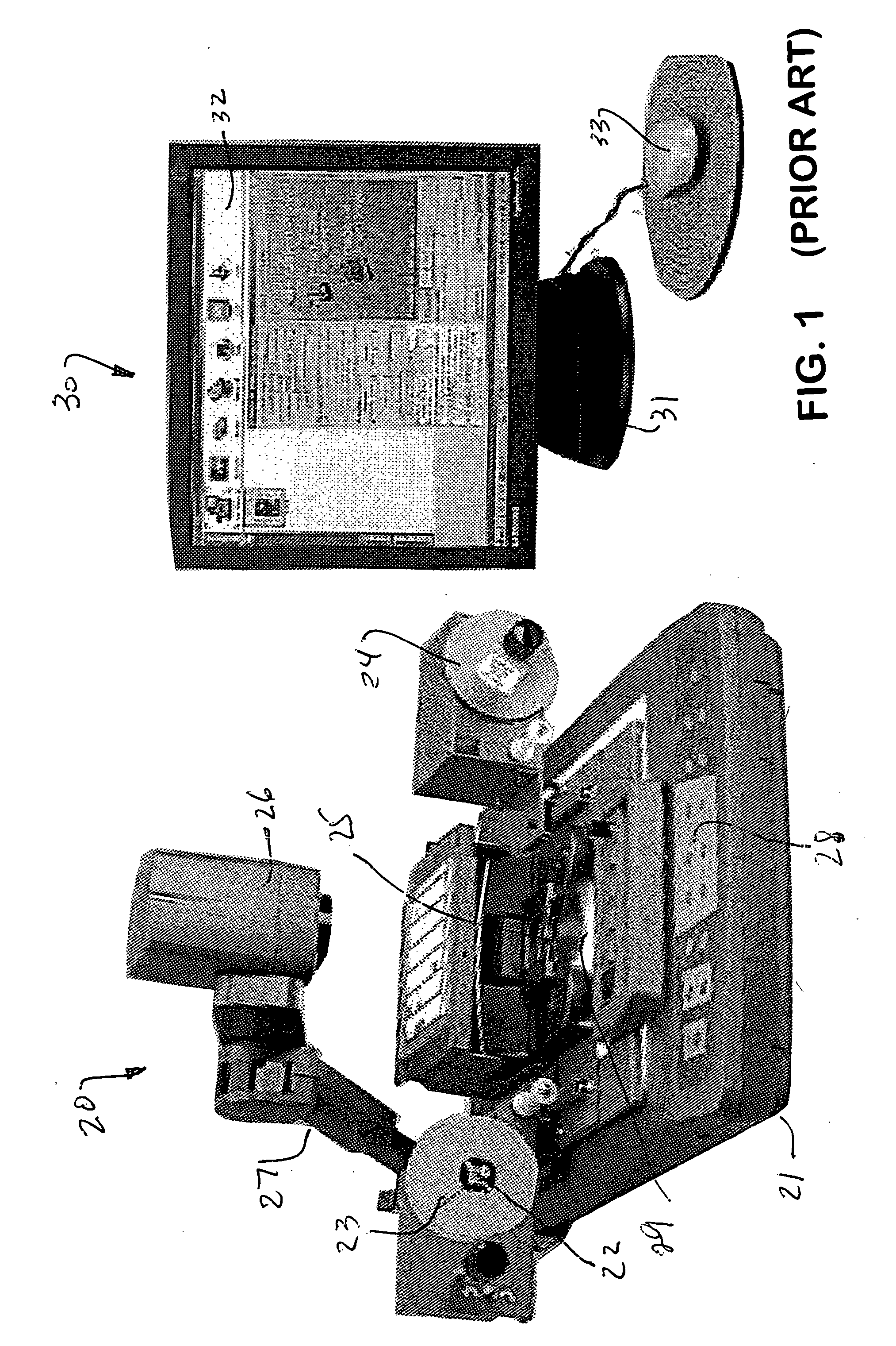
[0032] With reference to the drawing Figures, FIG. 1 illustrates a digital microfilm viewing and scanning system, generally designated 20, for digitally viewing and then scanning a microfilm medium, and a viewing device, generally designated 30, for viewing of a live video feed of an image and / or of an image scanned by viewer / scanner 20. Both viewer / scanner 20 and viewing device 30 each have a base 21 and 31, respectively, for placement of viewer / scanner 20 and viewing device 30 on a desk, table or the like. On one side of viewer / scanner 20, a roll of microfilm 23 may be mounted on a spindle 22. The microfilm on roll 23 is mounted on spindle 22 and threaded through a...


PUM


Abstract

Apparatus for remotely viewing and scanning microfilm at a first location, while controlling the viewing and scanning from a remote location, including a viewing and scanning device for generating a video feed and subsequently scanned images of the microfilm, a host computer at the first location in communication with the viewing and scanning device to receive the video feed and the scanned images, a user's computer at a remote location in communication with the host computer to receive the video feed and the scanned images from the host computer, and a virtual film movement control at the user's computer to control the movement of the microfilm at the first location. A virtual camera control at the remote location controls the camera of the viewing and scanning device.

Description

FIELD OF THE INVENTION [0001] The present invention relates generally to apparatus and methods for viewing and scanning of microfilm. [0002] More particularly, the present invention relates to improved apparatus and methods that provide for viewing and scanning of microfilm and the like from a remote location. BACKGROUND OF THE INVENTION [0003] Collections and libraries of images and documents exist on microfilm in many locations throughout the world. Many documents and other images have been placed on microfilm over the past several decades. In many instances, certain documents may only be available from microfilm. The microfilm media may be in various forms including cartridges, rolls and microfiche cards. For example, documents in the typical 8 inch by 11½ inch page format are frequently stored on 16 mm cartridges. Large engineering and architectural drawings are typically stored on 35 mm media. Of course, older collections may be on microfiche cards. Existing microfilm readers t...

Claims


Application Information

Patent Timeline
IPC IPC(8): H04N1/04
CPCG03B21/118H04N1/00132H04N1/00135H04N1/00137H04N1/00145H04N1/00164H04N1/00188H04N1/00193H04N1/00347H04N2201/0013H04N2201/0039H04N2201/0075H04N2201/0081H04N2201/0089H04N2201/041
Inventor ANDERSON, THOMAS P. JR.DONALDSON, DANIEL J.
Owner DIGITAL CHECK CORP
Learn More