Rotating constrained liner

a technology of constrained liner and prosthetic hip joint, which is applied in the field of constrained liner for prosthetic hip joint, can solve the problems of reducing the range of motion of the prosthetic hip joint, subluxation, and even dislocation, and the potential impact of hip prosthesis

Inactive Publication Date: 2007-05-10
ZIMMER TECH INC
View PDF48 Cites 21 Cited by
  • Summary
  • Abstract
  • Description
  • Claims
  • Application Information

AI Technical Summary

Problems solved by technology

Hip prostheses can potentially experience impingement, subluxation, and even dislocation after being implanted in the patient.
Conventional constrained liners, while providing additional stability to the prosthetic hip joint, inherently reduce the range of motion of the prosthetic hip joint because the femoral neck of the femoral component impinges on the extended portions of the constrained liner which extend beyond the hemispherical shape.

Method used


Image

  • Rotating constrained liner
  • Rotating constrained liner
  • Rotating constrained liner

Examples


Embodiment Construction

[0026] The embodiments disclosed below are not intended to be exhaustive or limit the invention to the precise forms disclosed in the following detailed description. Rather, the embodiments are chosen and described so that others skilled in the art may utilize their teachings.

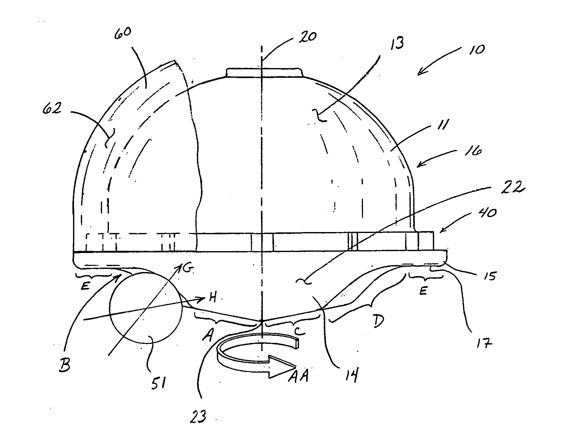
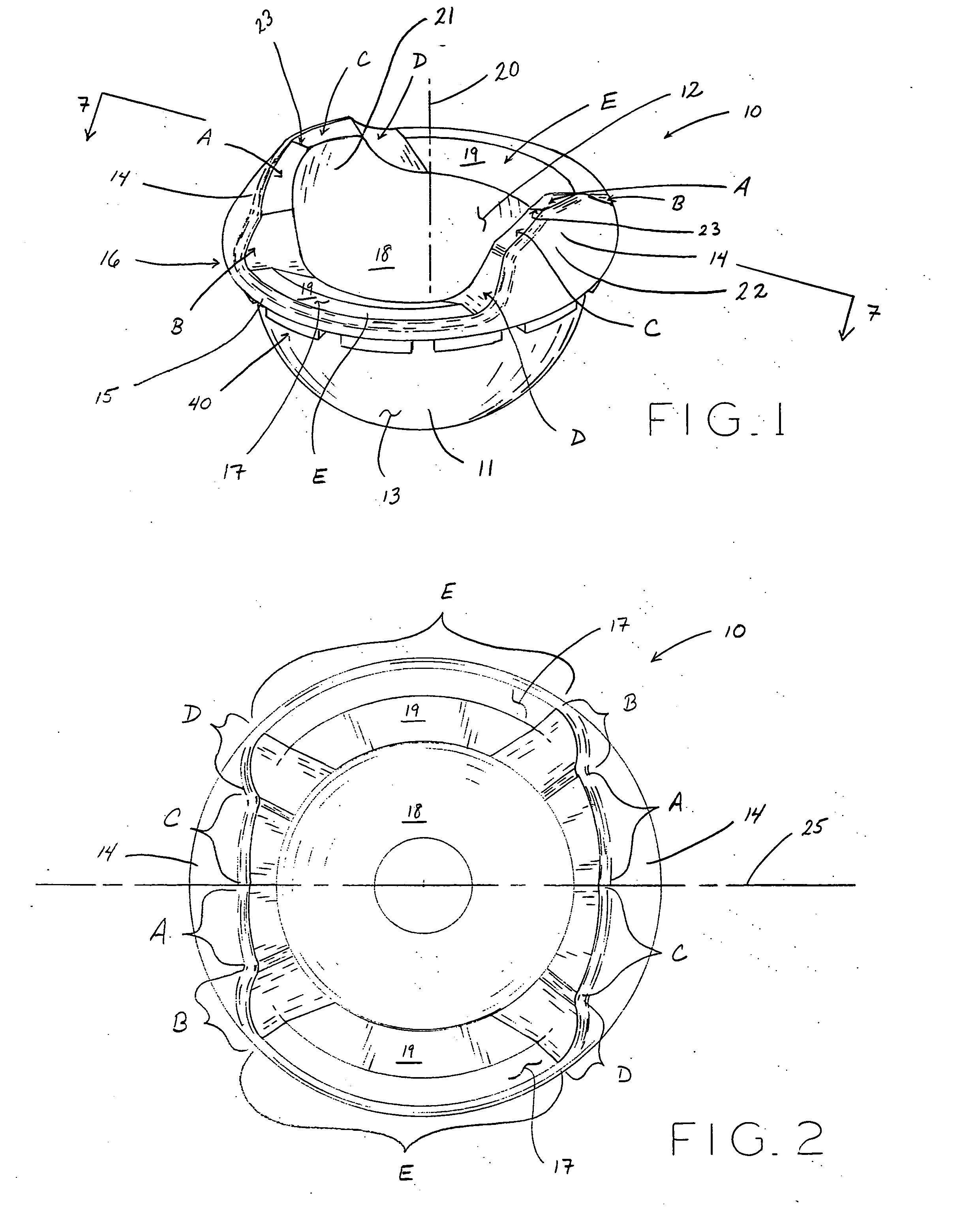
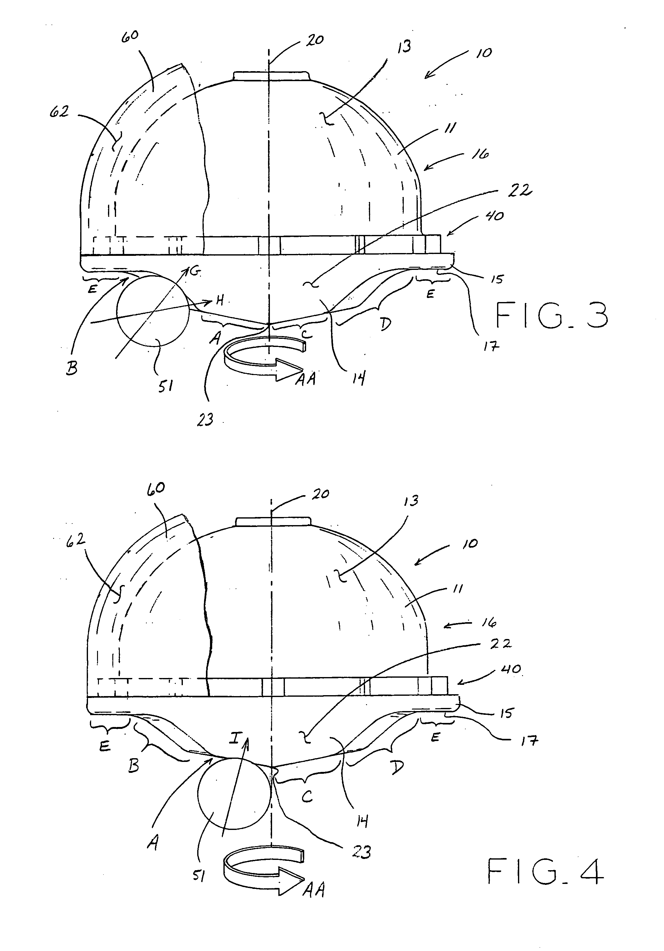
[0027] Referring now to FIG. 1, an exemplary rotating constrained liner 10 is shown including cup portion 11 and a pair of constraining portions 14. As described below, liner 10 is received within acetabular shell 60 (FIG. 8A) of a prosthetic hip joint assembly which additionally includes a femoral prosthesis having a femoral head and a femoral neck. The femoral head of the femoral prosthesis is positioned within liner 10. Cup portion 11 generally has a partially spherical or dome-shaped body with outer surface 13 and inner surface 12. Inner surface 12 defines a partial spherical or hemispherical cavity 18 for receiving a femoral head or ball 52 (FIG. 7) of a femoral component 50 (FIG. 7). Inner surface 12 has...


PUM


Abstract

An acetabular component for a prosthetic hip joint generally consists of an acetabular shell and an acetabular liner. The acetabular liner includes a cup portion and at least one constraining portion. The cup portion has a hemispherical or dome-shape that defines a hemispherical cavity for receiving a femoral head of a femoral component. The constraining portions may include extensions for retaining the femoral head in the cavity of the cup portion. The liner further includes cutout portions between the constraining portions. The acetabular liner is rotatable within the acetabular shell to provide a complete range of motion to the femoral component without fear of impingement, subluxation, or dislocation of the femoral head. The constraining portions may include inclined surfaces to induce rotation of the acetabular liner within the acetabular shell.

Description

BACKGROUND [0001] 1. Field of the Invention The present invention relates to a constrained liner for a prosthetic hip joint, and, more particularly, to a rotating constrained liner for a prosthetic hip joint. [0002] 2. Description of the Prior Art [0003] Acetabular prostheses generally consist of two separate components, an acetabular shell and an acetabular liner. The shell has a hemispherical shape and is affixed and embedded into a cavity formed in a natural acetabulum of a patient. The liner has a hemispherical shape to mate with an internal cavity of the shell. A low-friction bearing surface is formed along a spherical cavity in the liner and provides an articulation surface for a femoral ball of a hip stem. [0004] The shell may be made of a biocompatible metal or metal alloy, and the liner may be made of a polymer, such as ultrahigh molecular weight polyethylene (UHMWPE). Regardless of the materials or geometries, these two components are generally locked together with the lin...

Claims


Application Information

Patent Timeline
Patent Type & Authority Applications(United States)
IPC IPC(8): A61F2/32A61F2/34
CPCA61F2/32A61F2/34A61F2/40A61F2002/30354A61F2002/30364A61F2002/30373A61F2002/30378A61F2002/30487A61F2002/30685A61F2002/30937A61F2002/3233A61F2002/325A61F2002/3291A61F2002/3409A61F2002/3411A61F2002/3443A61F2002/3491A61F2002/3611A61F2002/3625A61F2002/4641A61F2220/0025A61F2220/0033A61F2310/00017A61F2310/00023A61F2310/00029A61F2002/30426A61F2002/30495A61F2002/305A61F2002/3241A61F2002/349
Inventor RICHARDS, MARK ISOM
Owner ZIMMER TECH INC
Why Eureka
Try Eureka