
Container end closure with pull tab

a technology of pull tabs and end closures, applied in the field of container and pull tab openers, can solve the problems of not being able to achieve the desired free lift, and achieve the effect of lessening the free lift for

Inactive Publication Date: 2007-05-17
SPARKTAB
View PDF11 Cites 40 Cited by
  • Summary
  • Abstract
  • Description
  • Claims
  • Application Information

AI Technical Summary

Benefits of technology

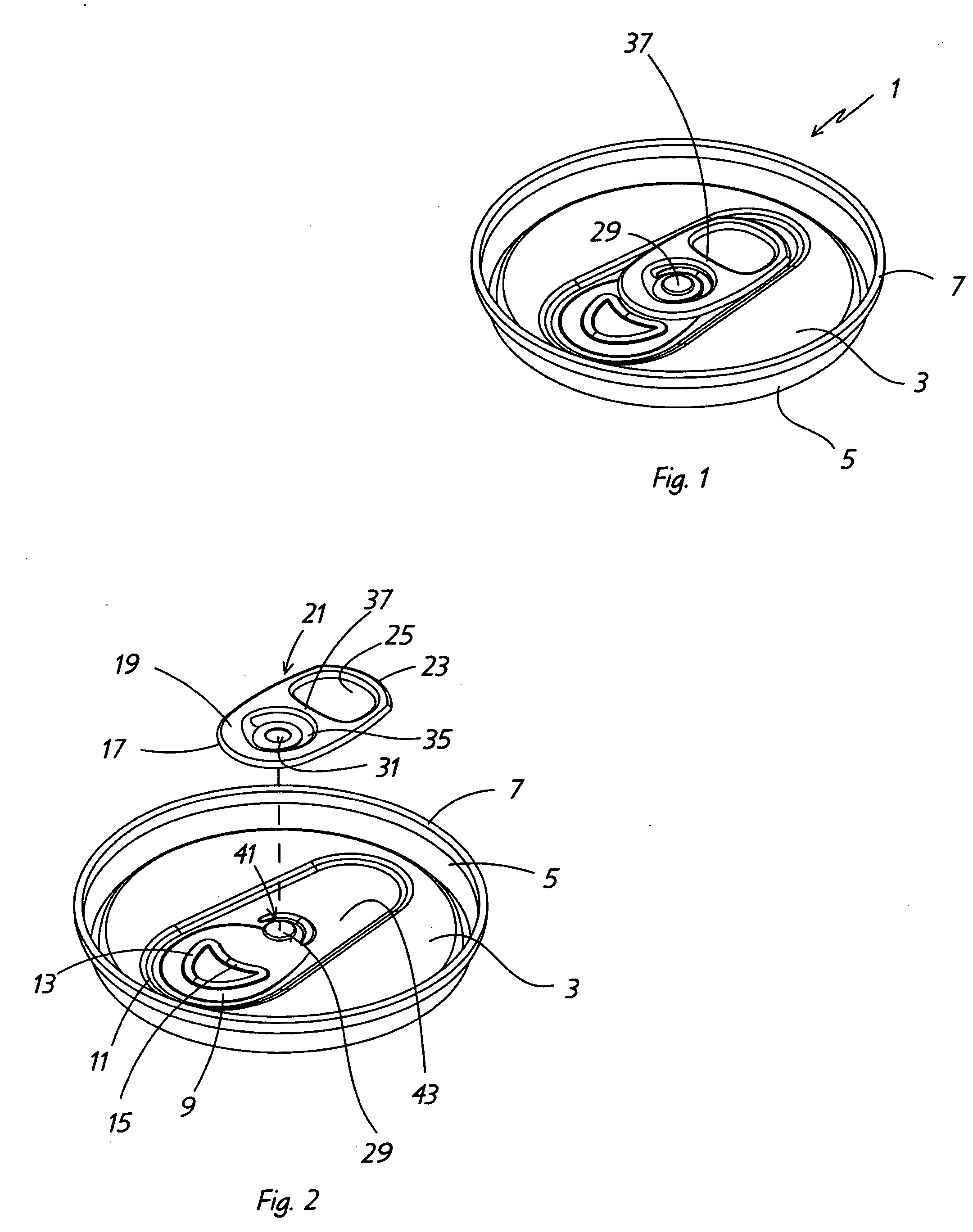
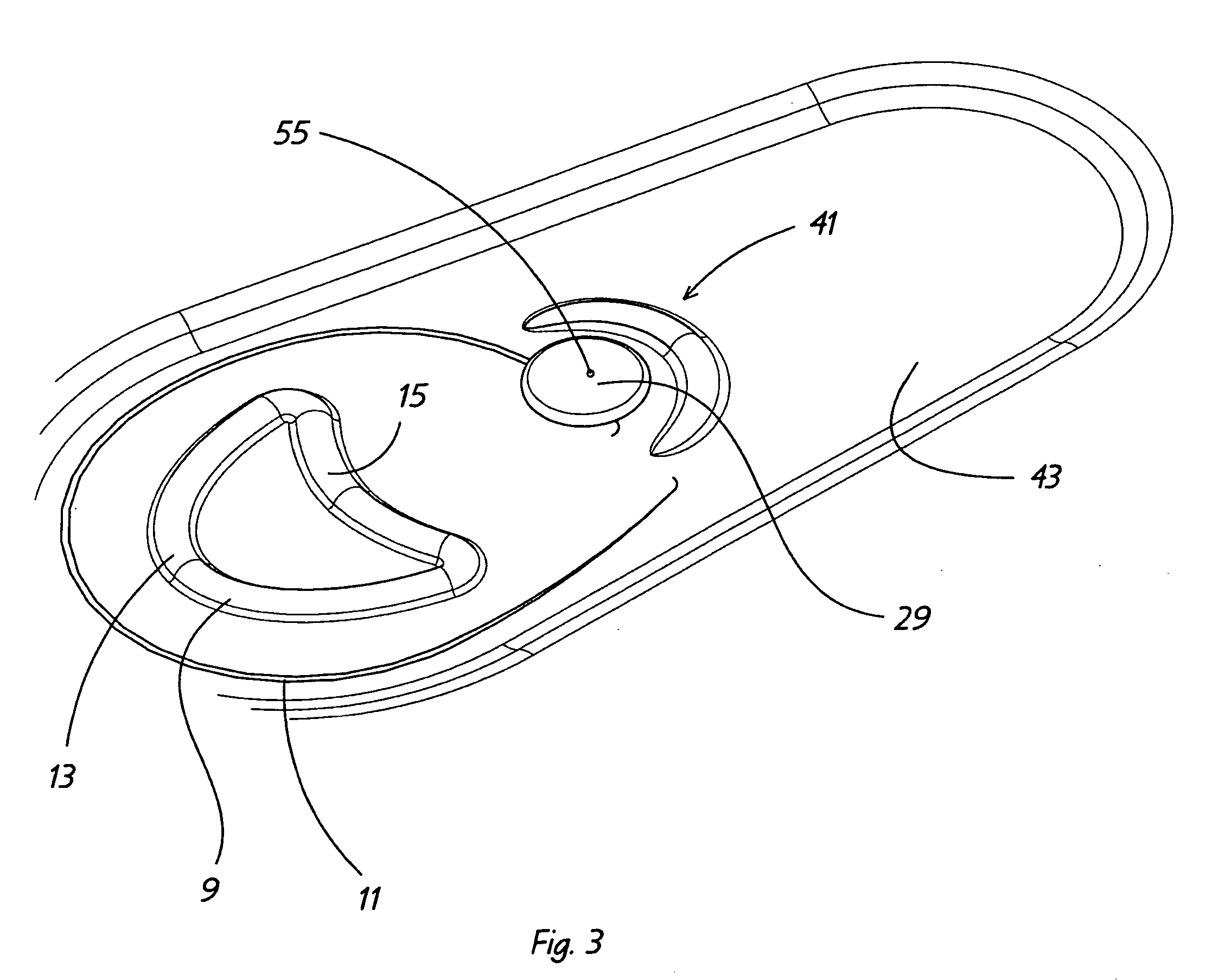
[0006] One aspect of the present invention is to provide a container end closure primarily for beverage containers, in which one or two C-shaped or crescent-shaped protrusions are formed in the central panel of the end closure located closely adjacent about the rear of the rivet, which protrusions will lessen the free lift forces required to lift the rear end of the tab, enabling the tab end to more easily be raised up and then pivoted about the rivet, whereby the nose of the tab engages the frangible panel.
[0008] A still further feature of the present invention is to form the crescent-shaped protrusions whereby the top center of the first protrusion is approximately 0.20 inches from the center of the rivet with the top center of the second protrusion lying approximately 0.25 inches from the center of the rivet, which distances are closer than the heretofore prior art protrusions and indentations to facilitate the pulling up of the rivet from the central panel to lessen the free lift forces and allow the rear of the tab to be more easily raised up prior to the nose of the rivet engaging the frangible panel.
[0010] A further feature of the invention is that the location of a first and / or second protrusion is either within an opening of the pull tab or beneath the pull tab to prevent interference with the can manufacturing equipment and to permit the tab to lay relatively flat against the end panel.

Problems solved by technology

Experience shows that this free lift is not as easy as desired in the container industry, and that numerous attempts have been made to reduce this free lift force without weakening the end closure and components thereof.

Method used


Image

  • Container end closure with pull tab
  • Container end closure with pull tab
  • Container end closure with pull tab

Examples


Embodiment Construction

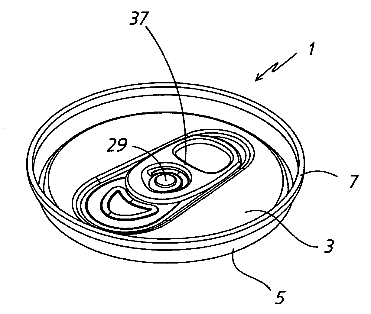
[0028] A first embodiment of the improved container end closure of the present invention is indicated generally at 1, and is shown in FIGS. 1-7 and 11. End closure 1 includes a central panel 3 having a generally circular shape which includes a circumferentially extending raised side wall 5 having an edge 7 for attaching end closure 1 to a suitable cylindrical container (not shown) in a manner well-known in the art.

[0029] In a preferred embodiment, end closure 1 will be formed of aluminum with central panel 3 having a thickness of approximately 0.007 inches. A usual tear panel 9 is formed in central panel 3 and defined by a frangible score line 11. Tear panel 9 includes a usual curved D-shaped protrusion 13 having an inner curved portion 15 which closely aligns with the curved outer end 17 of tab nose 19 of a usual pull tab, indicated generally at 21. Tab 21 is of a usual construction well-known in the beverage can art, having nose 17 and a rear curved lift end 23. Lift end 23 is gr...


PUM


Abstract

An easy opening end closure for a container has a central panel with a tear panel defined by a score line. A pull tab is attached by a rivet to the central panel and has a nose end for engaging the tear panel and an opposite lift end for pivoting the tab about the rivet to fracture the score line. One or a pair of crescent-shaped protrusions are formed on the central panel closely adjacent to and rearwardly of the rivet to reduce the lift force required to initially lift the lift end of the tab to start the fracturing of the score line. The protrusions are concentric to each other and partially circumscribe the rivet and are located beneath the pull tab or within openings of the pull tab to avoid interference with can making equipment and with the pull tab. The protrusions provide greater flexibility to the area of the central panel adjacent the rivet to enable the rivet to pull slightly upwards from the panel at the start lifting the lift end of the tab.

Description

BACKGROUND OF THE INVENTION [0001] 1. Technical Field [0002] The invention relates to containers and pull tab openers therefore. In particular, the invention relates to a pull tab opener formed with one or more protrusions in the central panel portion of the end closure approximate the rivet which reduce the force required to lift up the back end of the tab for subsequent breakage of the frangible panel from the end closure. [0003] 2. Background Information [0004] Millions of aluminum containers are produced each year, usually for storing beverages. These containers have a pull tab for separating a tear panel from the central panel of the end closure to provide access to the contents of the container. These pull tabs are attached to the central panels of the end closures by rivets which are usually formed integral with the end closure. At one side of the rivet opposite the outer end of the pull tab, is a scored opening which is a push-in closure which seals the can and withstands th...

Claims


Application Information

Patent Timeline
IPC IPC(8): B65D17/34
CPCB65D17/165B65D2517/0011B65D2517/007B65D2517/0071B65D17/4012
Inventor DICKIE, ROBERT G.
Owner SPARKTAB
Learn More