Seal System

Active Publication Date: 2013-04-18
WATERMAN IND +1
View PDF1 Cites 4 Cited by
  • Summary
  • Abstract
  • Description
  • Claims
  • Application Information

AI Technical Summary

Benefits of technology

[0012]Accordingly, a broad object of the invention can be to provide a seal system for a slide gate which self adjusts or self conforms into sealing relation

Problems solved by technology

However, these conventional top seals when engaged with the face of the gate have substantial frictional drag which must be overcome by a substantially greater lifting force in operation of the slide gate.
Additionally, conventional top seals may collect debris because of the width of the sides.
The debris can abrade the surface of the top seal and the surface of the gate causing a leak path or reducing the life of the top seal.
Because conventional seals require adjustment of a plurality of parts to seal and do not seal by self conforming to the opposed faces of the gate, installation and maintenance costs of conv

Method used


Image

  • Seal System
  • Seal System
  • Seal System

Examples


Embodiment Construction

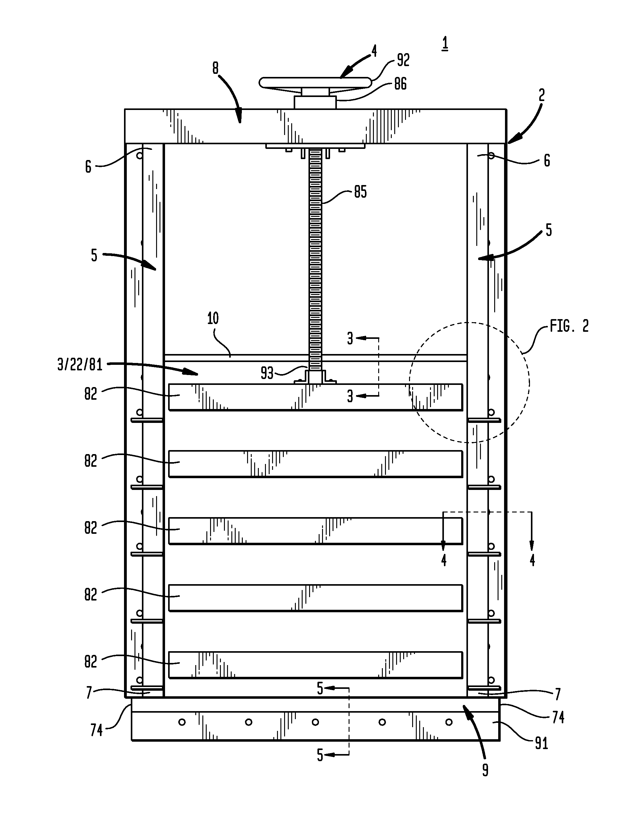
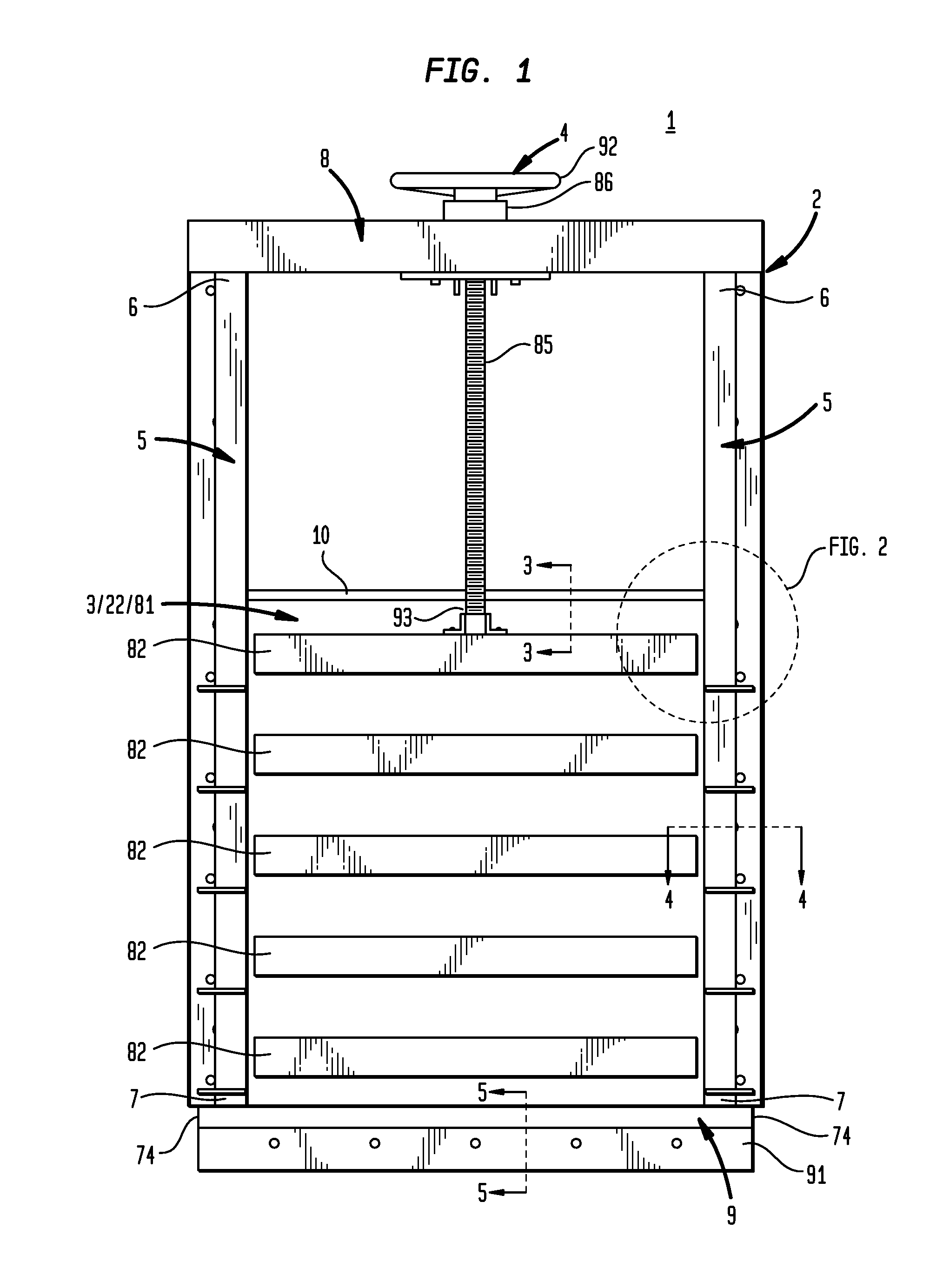
[0023]Now referring primarily to FIG. 1, an exemplary slide gate (1) includes a frame assembly (2), a gate (3), and a gate operator (4). The frame assembly (2) includes a pair of gate guide members (5) disposed in substantially parallel relation a distance apart each having a length between a first end (6) and a second end (7), a top frame member (8) coupled between the pair of gate guide members (5) proximate the first ends (6), a bottom frame member (9) coupled between the pair of gate guide members (5) proximate second ends (7), and an intermediate cross member (10) coupled between the pair of gate guide members (5) at a height between the bottom frame member (9) and the top frame member (8).

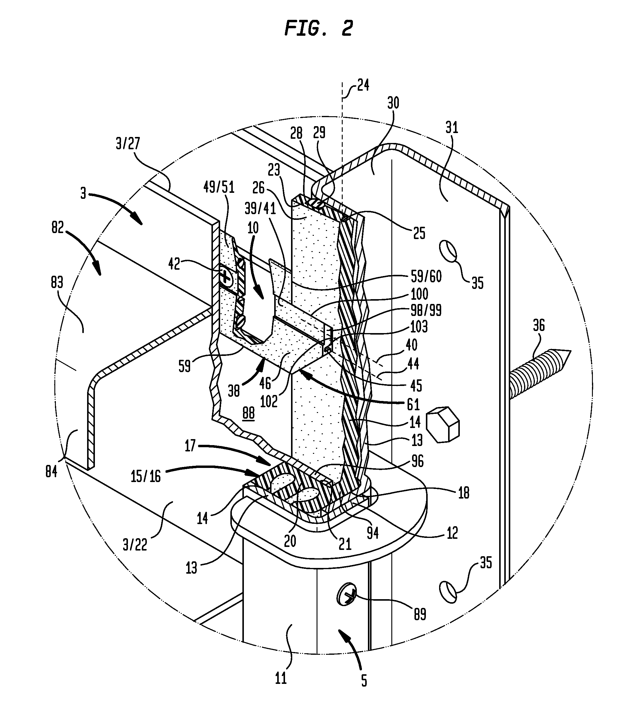
[0024]Now referring primarily to FIGS. 2 and 4, each of the pair of gate guide members (5) in part include a side channel element (11) (which can be formed as a single piece or by coupling of two pieces as shown in FIG. 2) defined by a bottom wall (13) and a pair of side walls (12). The pair ...


PUM

PropertyMeasurementUnit
Lengthaaaaaaaaaa
Angleaaaaaaaaaa
Flow rateaaaaaaaaaa

Abstract

A slide gate for controlling fluid flow having improved slide gate seals.

Description

[0001]This U.S. Non-Provisional Patent Application claims the benefit of U.S. Provisional Patent Application No. 61 / 627,504, filed Oct. 13, 2012, hereby incorporated by reference herein.I. BACKGROUND[0002]A slide gate for controlling fluid flow having improved slide gate seals.[0003]Conventional slide gates are employed to control fluid flow through a passageway or channel. Conventional slide gates typically provide a frame assembly which defines an opening through which fluid flows, a gate slidely mounted to the frame assembly, and a gate operating means for generating movement in the gate between an open position and a closed position for regulating fluid flow through the opening.[0004]As to particular conventional slide gates, the frame assembly can be mounted to walls which define a passageway or channel through which the fluid flows such that substantially all of the fluid flows through the opening in the frame assembly. In this way, fluid flow through the opening of the gate c...

Claims


Application Information

Patent Timeline
IPC IPC(8): F16K3/00B21D53/00
CPCF16K3/0227Y10T29/49405F16K3/316F16K3/0281
Inventor MIKESELL, KENNETH W.PAULS, DARRYL RAY
Owner WATERMAN IND
Why Eureka
Try Eureka