
Closure unit

a closure unit and vertical closing technology, applied in the field of vertical closing closure units, can solve the problems of force-locking restraint devices such as redundant clamping devices, which are on the one hand costly and on the other hand have to be regularly checked, and are naturally detrimental to productivity

Active Publication Date: 2016-09-27
ENGEL AUSTRIA
View PDF17 Cites 5 Cited by
  • Summary
  • Abstract
  • Description
  • Claims
  • Application Information

AI Technical Summary

Benefits of technology

The invention is a restraint device that locks a moveable mold mounting plate to a frame bar, reducing the number of components and improving safety and security. Additionally, the device allows for upward restraint of the mold mounting plate to ensure safe access for operating personnel. The device is controlled by a control unit that activates the restraint upon receiving a signal indicating a failure of the closure unit or an instruction from an operator. The technical effect of the invention is to improve safety, security, and reduce production costs.

Problems solved by technology

Force-locking restraint devices like, for example, redundant clamping devices are on the one hand costly and on the other hand have to be regularly checked—generally once a month.
That is naturally detrimental to productivity.

Method used


Image

  • Closure unit
  • Closure unit
  • Closure unit

Examples


Embodiment Construction

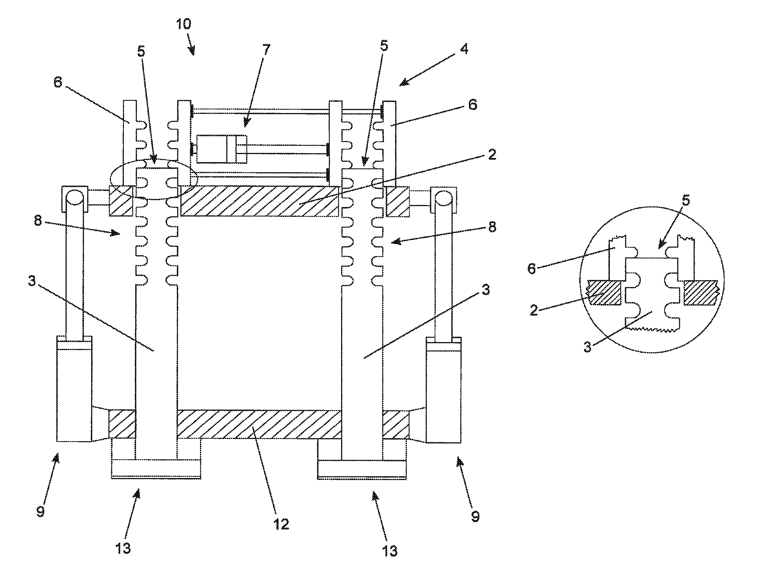
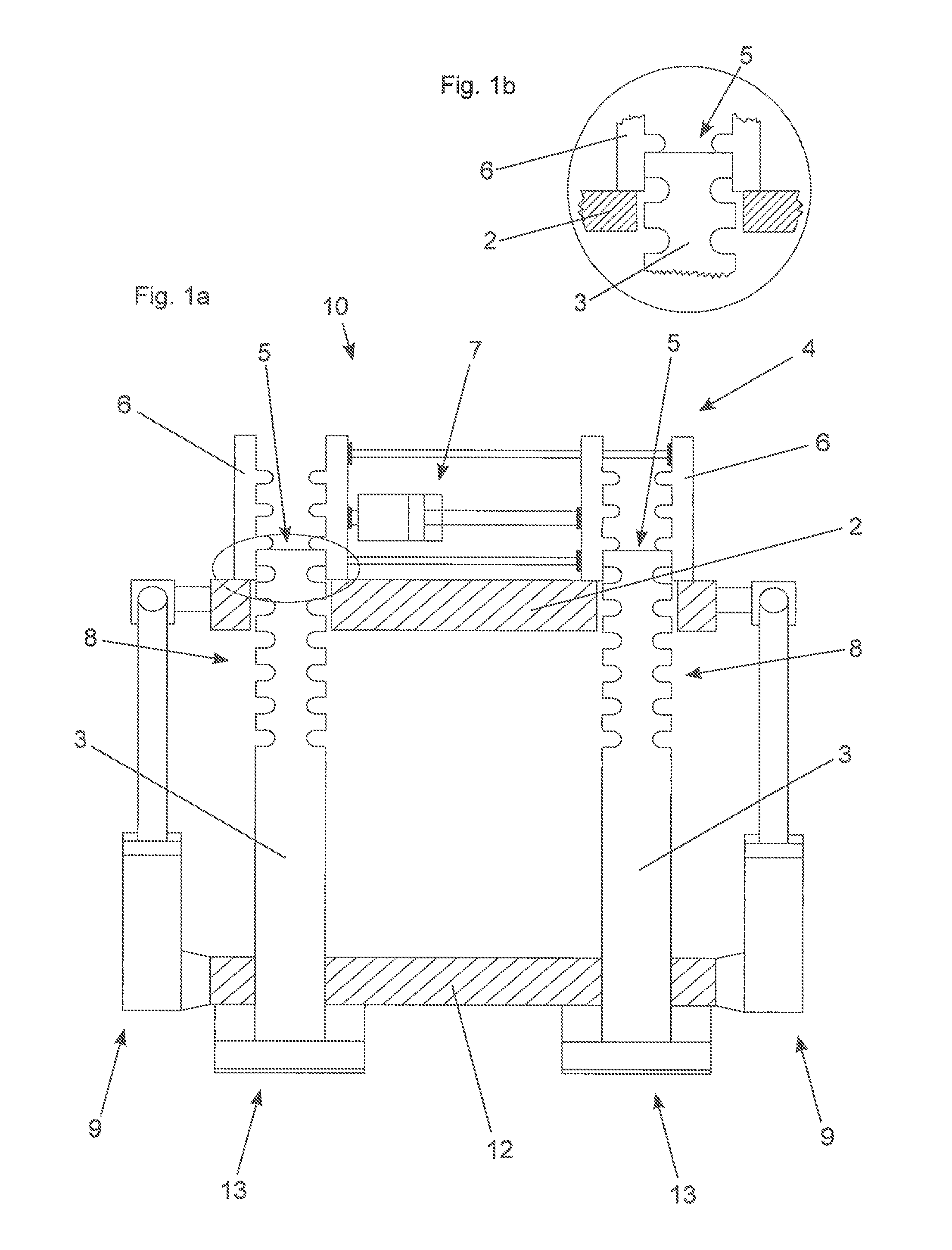
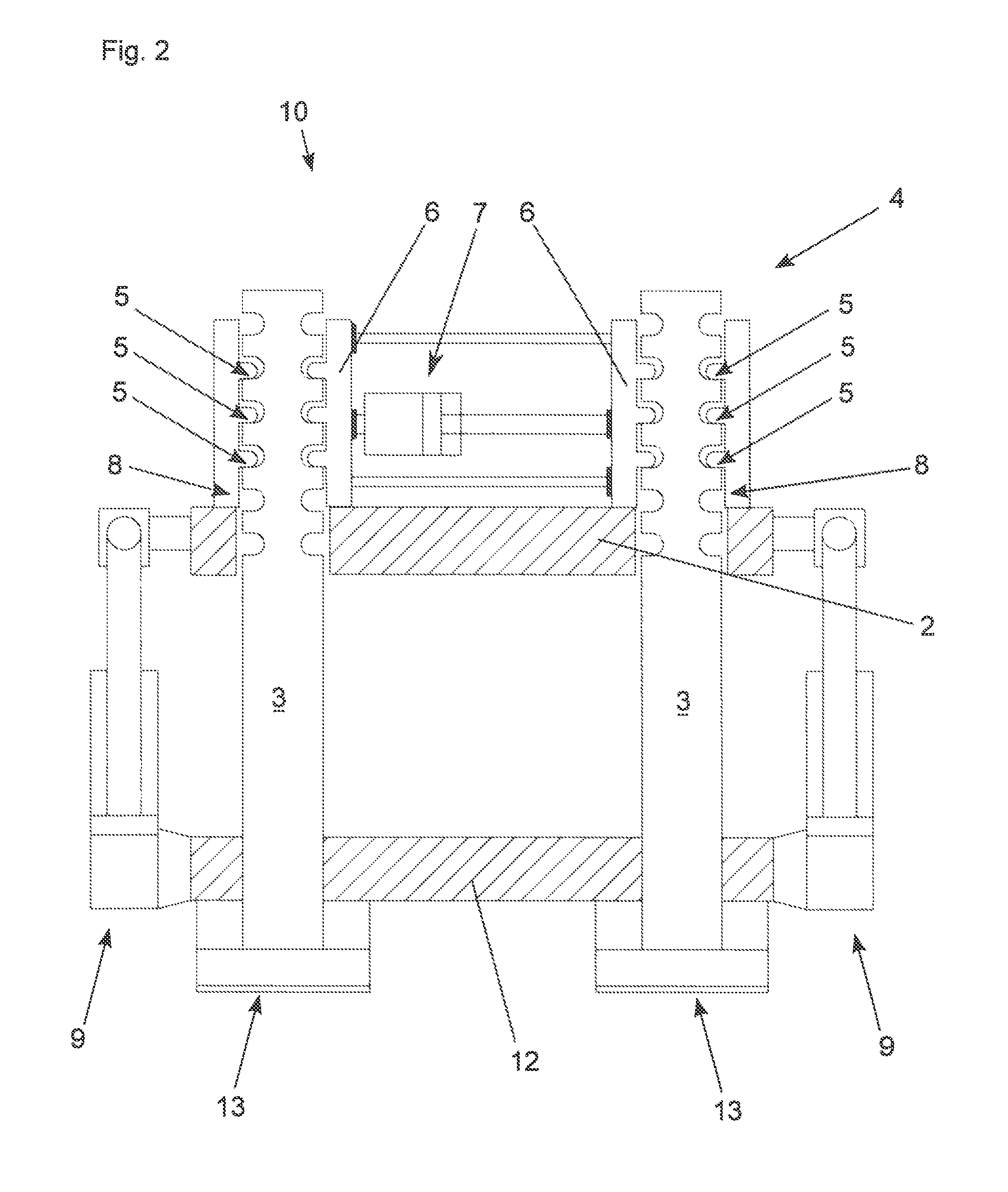
[0027]In the closure unit 10 diagrammatically shown in FIG. 1a, it is possible to see firstly the fixed mold mounting plate 12, the moveable mold mounting plate 2, the frame bars 3, the rapid-action devices 9, the pressure cushions 13, and the upward (vertical) restraint device 4. As would be clear to one skilled in the art based on the description herein, the terms “upward” and “vertical” refer to the movement of the moveable mold mounting plate 2 along and relative to the frame bars 3. In this case, the restraint device 4 comprises a respective divided locking nut 6 for each frame bar 3 and a locking drive 7 for two respective locking nuts 6. The locking drive 7 is hydraulic in the embodiment. The locking nuts 6 are fixed to the moveable mold mounting plate 2.

[0028]In this case, at least the support surface 5 is formed by the top side of the frame bars 3. This can better be seen from the detail view in FIG. 1b showing a flank of an inside profile of a locking nut 6 resting on the ...


PUM

PropertyMeasurementUnit
force of gravityaaaaaaaaaa
pressureaaaaaaaaaa
unlocking forceaaaaaaaaaa

Abstract

A vertically closing closure unit for an injection molding machine includes a moveable mold mounting plate, and at least one frame bar for guiding the moveable mold mounting plate. A vertical restraint device holds and locks the moveable mold mounting plate to the at least one frame bar.

Description

BACKGROUND OF THE INVENTION[0001]The present invention concerns a vertically closing closure unit for an injection molding machine.[0002]For safety reasons, vertically closing closure units of injection molding machines must have restraint devices which prevent a moveable mold mounting plate from dropping down due to gravity if a defect, for example in the rapid-action mechanism, occurs. In the state of the art they are mounted to the rapid-action devices. In particular, in the case of hydraulic rapid-action devices, the restraint devices are in the form of clamping devices which if required act directly at the rapid-action cylinders. A basic problem with such restraint devices is that, in the event of structural failure of certain components of the rapid-action device or the restraint devices—for example fracture of fixing pins—the moveable mold mounting plate nonetheless drops down. This means that such components have to be over-sized to afford a certain safety cushion. Naturally...

Claims


Application Information

Patent Timeline
Patent Type & Authority Patents(United States)
IPC IPC(8): B29C45/84B29C45/67
CPCB29C45/84B29C45/6728Y10T29/49826
Inventor ZEIDLHOFER, HERBERTLOHNECKER, ANTON
Owner ENGEL AUSTRIA
Learn More