Lifting device for a display

Inactive Publication Date: 2007-05-17
OKNINSKI MAREK
View PDF7 Cites 27 Cited by
  • Summary
  • Abstract
  • Description
  • Claims
  • Application Information

AI Technical Summary

Benefits of technology

[0020] According to another exemplary embodiment, an elevating apparatus is provided comprising a mounting frame; a first movable frame linearly movable within the mounting frame; and a second movable frame to support an object, the second movable frame being slidably engaged along the first movable frame to provide a movable frame configuration. A linear actuator engages the first movable frame so as to raise and lower the first movable frame. At least a first pulley and a second pulley are attached to the first movable frame and at least one pliable member which engages the first pulley and the second pulley, wherein one side of the pliable member is coupled to a lower portion of the mounting frame and another side of the pliable member is coupled with

Problems solved by technology

This is done because in many cases, the back of the furniture is made out of ¼″ thick MDF or Flake Boar

Method used


Image

  • Lifting device for a display
  • Lifting device for a display
  • Lifting device for a display

Examples


Example

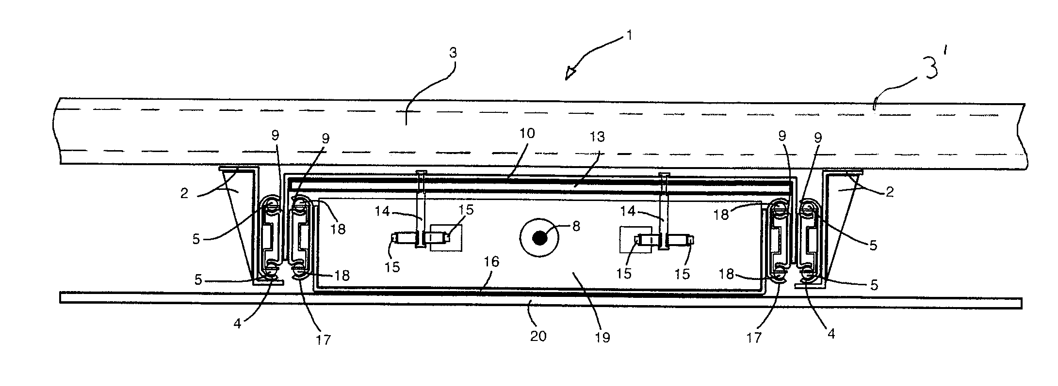
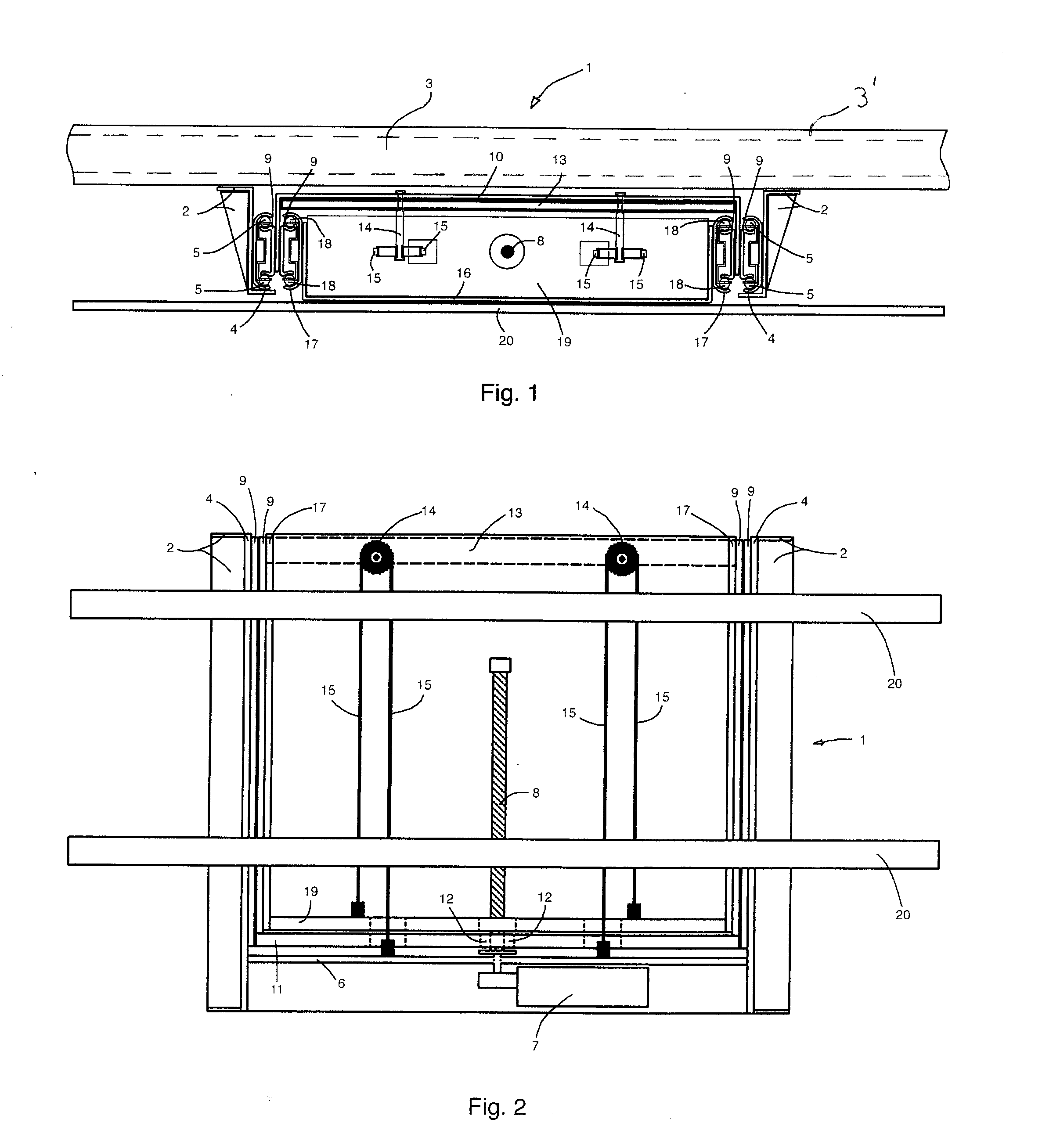
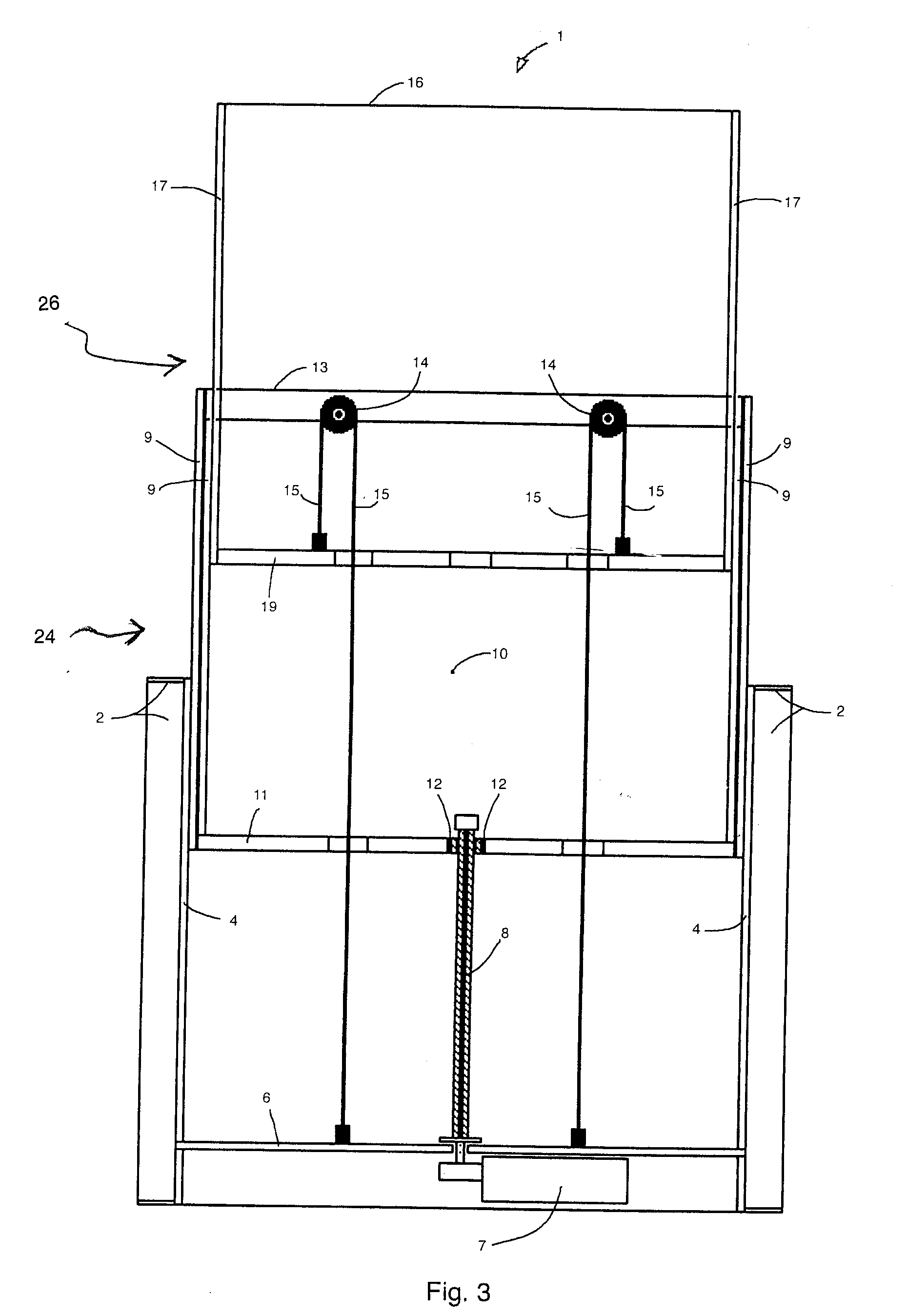
[0039] Referring now to the FIGS. 1-3, an elevating apparatus 1 is shown having a pair of lift-mounting brackets 2 mounted to a mounting panel 3, and a pair of outer slide members 4 attached to the lift-mounting brackets 2. A stabilizing bar 3′ may also be added along a top of the mounting panel 3 to aid in resisting bending moments exerted upon the mounting panel 3. A horizontal motor-mount bar 6 is attached to the lift-mounting brackets 2, and a single shaft right angle gear motor 7 is mounted to the motor-mount bar 6. A single vertical threaded rod 8 is mounted to a shaft of gear motor 7. Two pairs of inner slide members 9 are attached to a back panel 10. Ball bearings 5 are disposed between the inner slide members 9 and the lift-mounting brackets 2. A horizontal bar 11 is attached to the back panel 10. A single threaded nut 12 is mounted on the vertical threaded rod 8 and attached to the horizontal bar 11. A sprockets / pulleys-bar 13 is attached to the back panel 10. A pair of sp...


PUM


Abstract

A device for lifting and lowering objects and electronic devices includes an elevating mechanism that elevates a first sliding frame and a second sliding frame. The first and second sliding frames move independently inside of a mounting frame. A linear actuator drives the first sliding frame and causes the first sliding frame to rise and fall. A belt and pulley configuration transfers an elevating force from the first sliding frame to the second sliding frame. The second or subsequent sliding frame is elevated to place the display or object at a desired height and may be retracted to conceal the display or object in a cabinet, or the like.

Description

[0001] This is a Continuation-in-Part of application Ser. No. 10 / 428,674 filed may 5, 2003. The entire disclosure of the prior application, application Ser. No. 10 / 428,674 is hereby incorporated by reference.BACKGROUND OF THE INVENTION [0002] 1. Field of the Invention [0003] The present invention relates to a device for lifting and lowering visual displays, such as television sets, video monitors, art pieces, flat plasma displays and the like. [0004] 2. Background of the Invention [0005] The development of television technology has been very progressive, with television sets becoming very large and thin. The most recent aspect of this technology is thin, flat plasma TV displays. Since it is preferable to hide a display when not in use, there is a need for a lifting device, which would enclose a plasma display within any type of cabinet, and elevate the display above such cabinet. Existing devices are esthetically unsightly or impractical. For example, U.S. Design Pat. No. 6,494,150 ...

Claims


Application Information

Patent Timeline
IPC IPC(8): B60J3/00A47B81/06
CPCA47B21/0073A47B81/064A47B2200/0069A47B2200/04A47B2220/0013
Inventor OKNINSKI, MAREK
Owner OKNINSKI MAREK
Why Eureka
Try Eureka