
Apparatus and method for conducting remote video inspection from above

a video inspection and remote technology, applied in the field of remote video inspection, can solve the problems of inconvenient use of pipe crawlers, a great deal of time to set up and operate, and the difficulty of adjusting the camera and the mast by hand, and achieves the effect of reducing the number of inspection cameras, reducing the difficulty of inspection, and increasing the difficulty of inspection

Active Publication Date: 2007-05-17
CT ZOOM TECH
View PDF23 Cites 22 Cited by
  • Summary
  • Abstract
  • Description
  • Claims
  • Application Information

AI Technical Summary

Benefits of technology

[0014] In accordance with a forth broad aspect of the present invention, there is provided a vehicle hitch mounting structure having a first and a second receivers. The first and second receivers comprise corresponding first and second longitudinal planes and first and second transversal planes. The first longitudinal plane is parallel to the second longitudinal plane and the first transversal plane is substantially perpendicular to the second transversal plane. Both first and second receivers are of the same type. Preferab

Problems solved by technology

It is sometimes necessary to inspect certain areas that are inconvenient and / or time-consuming to access.
Although effective in obtaining detailed images, using a pipe crawler is inconvenient and requires a great deal of time to set up and operate, even if no problems are discovered.
Suspending the camera and mast by hand requires much manipulation and becomes rapidly tiring.
Known vehicle mounted inspection cameras have a major drawback however.
Since the camera and mast are lowered vertically from the vehicle, they are not capable of adequately reaching lateral sewer pipes that are offset from the manhole.
Although most manholes are positioned squarely above the lateral conduits that they access, some manholes are substantially offset, generally because of an obstacle being in the way.
In many municipalities, approximately 10% of the underground piping network does not receive proper routine inspection with known equipment because the pipes are offset from the manholes that access them.

Method used


Image

  • Apparatus and method for conducting remote video inspection from above
  • Apparatus and method for conducting remote video inspection from above
  • Apparatus and method for conducting remote video inspection from above

Examples


Embodiment Construction

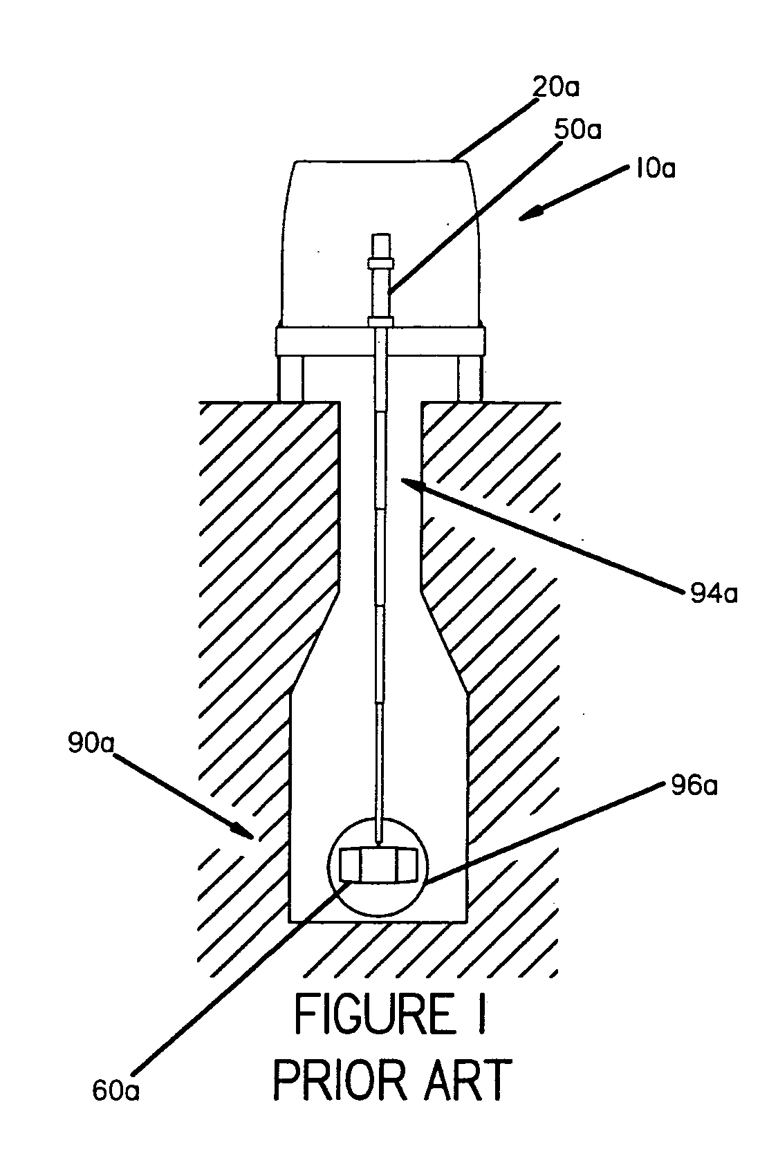
[0024]FIG. 1 depicts an example of prior art. In this example, an inspection system 10a is mounted to a vehicle 20a having a telescoping mast 50a deployed through a manhole 94a such that a video imaging system 60a is able to reach the lateral conduit 96a.

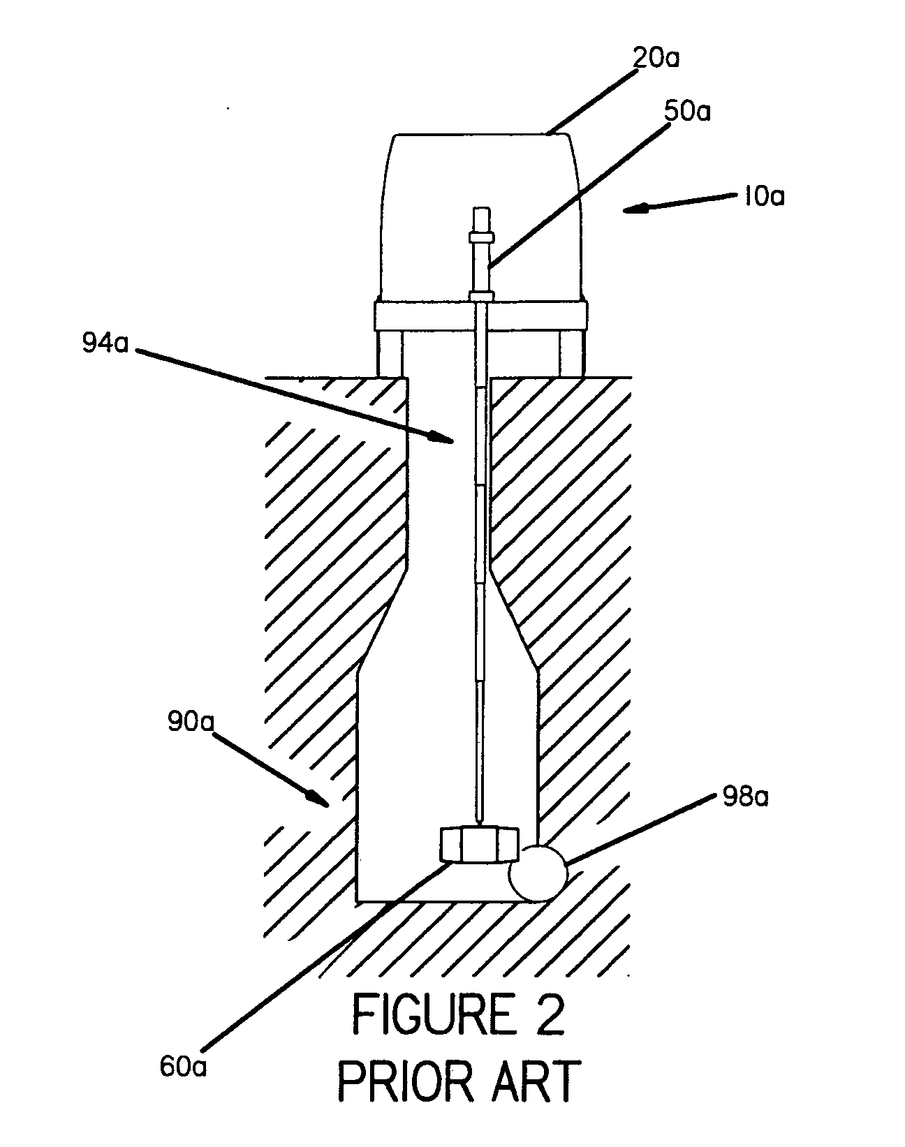
[0025]FIG. 2 depicts the same example of prior art inspection system as in FIG. 1 trying to reach an offset lateral conduit 98a this time. It is apparent that even by positioning the vehicle 20a as close as possible to the side of the manhole 94a, it is not possible for the imaging system 60a to reach the center of the offset lateral conduit 98a.

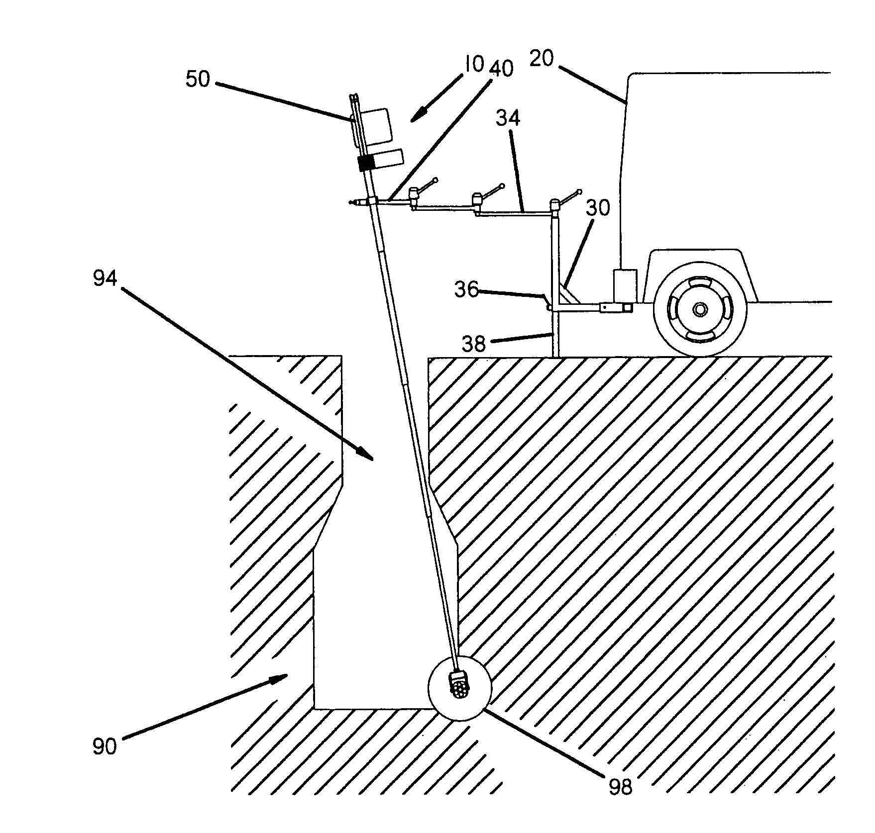
[0026]FIG. 3 shows an embodiment of the present invention reaching a similarly offset lateral conduit 98 as the offset lateral conduit 98a depicted in the prior art system of FIG. 2. It is possible to see that by using the features of the present invention, it is now possible for the video imaging system 60 to reach an offset lateral conduit 98, even when not locating vehicle 20 precisely ...


PUM


Abstract

An apparatus for conducting remote subsurface inspections from above is disclosed. The apparatus comprises a support structure having a fitting to secure the apparatus to a hitch receiver installed on a vehicle, a telescoping mast held by a coupling and born by the support structure and an imaging system held by an extendable portion of the telescoping mast. The apparatus may further comprise an articulating radial arm with pivots for locating the telescoping mast and an offsetting mechanism. A method for conducting remote subsurface inspections from above is also disclosed. The method of inspection comprises the steps of locating an access point on a working surface, positioning an apparatus for conducting remote subsurface inspections from above, manipulating the telescoping mast above the access point, lowering it and reviewing images from the imaging system.

Description

FIELD OF THE INVENTION [0001] The present invention generally relates to the remote inspection of areas that are difficult to reach. More specifically, the invention relates to inspection of underground sewers, railroad bridge support structures and other facilities that may be examined remotely from a location above, using a video camera or other imaging system. BACKGROUND OF THE INVENTION [0002] It is sometimes necessary to inspect certain areas that are inconvenient and / or time-consuming to access. For illustrative purposes, the inspection of storm and sewer pipes will be described, although the scope of the present invention is by no means limited to this application. Most municipalities contain a vast network of storm and sewer pipes. Periodically, these pipes must be inspected for problems such as cracks, blockage, build-up, and root infiltration. If a problem is detected, detailed images must be obtained to facilitate planning to remedy the situation. To this end, it is commo...

Claims


Application Information

Patent Timeline
IPC IPC(8): H04N7/18
CPCE03F7/12H04N7/183E21B47/0002H04N2005/2255E21B47/002H04N23/555
Inventor LORTIE, ALAIN
Owner CT ZOOM TECH
Learn More