Wheel caster with wheel chock

Inactive Publication Date: 2007-05-24
JOHNDREAU STEVEN S
View PDF20 Cites 3 Cited by
  • Summary
  • Abstract
  • Description
  • Claims
  • Application Information

AI Technical Summary

Benefits of technology

[0008] It is an object of the present invention to overcome the drawbacks and shortcomings of conventional wheel casters for conventional standing sports equipment. Particularly, most conventional standing sports equipment devices do not provide an efficient way to move the equipment from a storag

Problems solved by technology

Particularly, most conventional standing sports equipment devices do not provide an e

Method used


Image

  • Wheel caster with wheel chock
  • Wheel caster with wheel chock
  • Wheel caster with wheel chock

Examples


Embodiment Construction

[0028] This application incorporates herein by reference U.S. Pat. No.: 7,042,309, issued on May 9, 2006, which relates to Casters for an Automatic Ball Throwing Device.

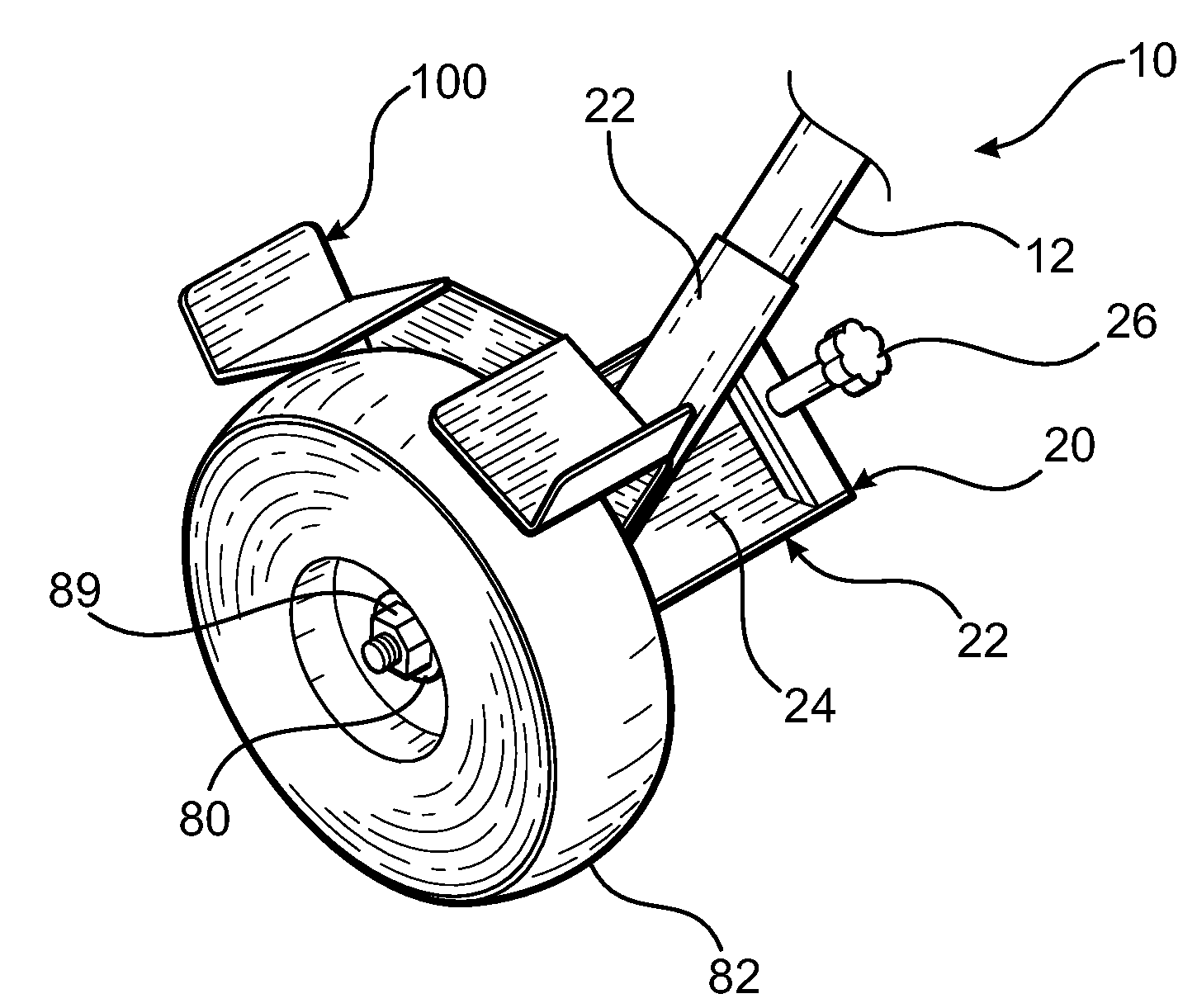
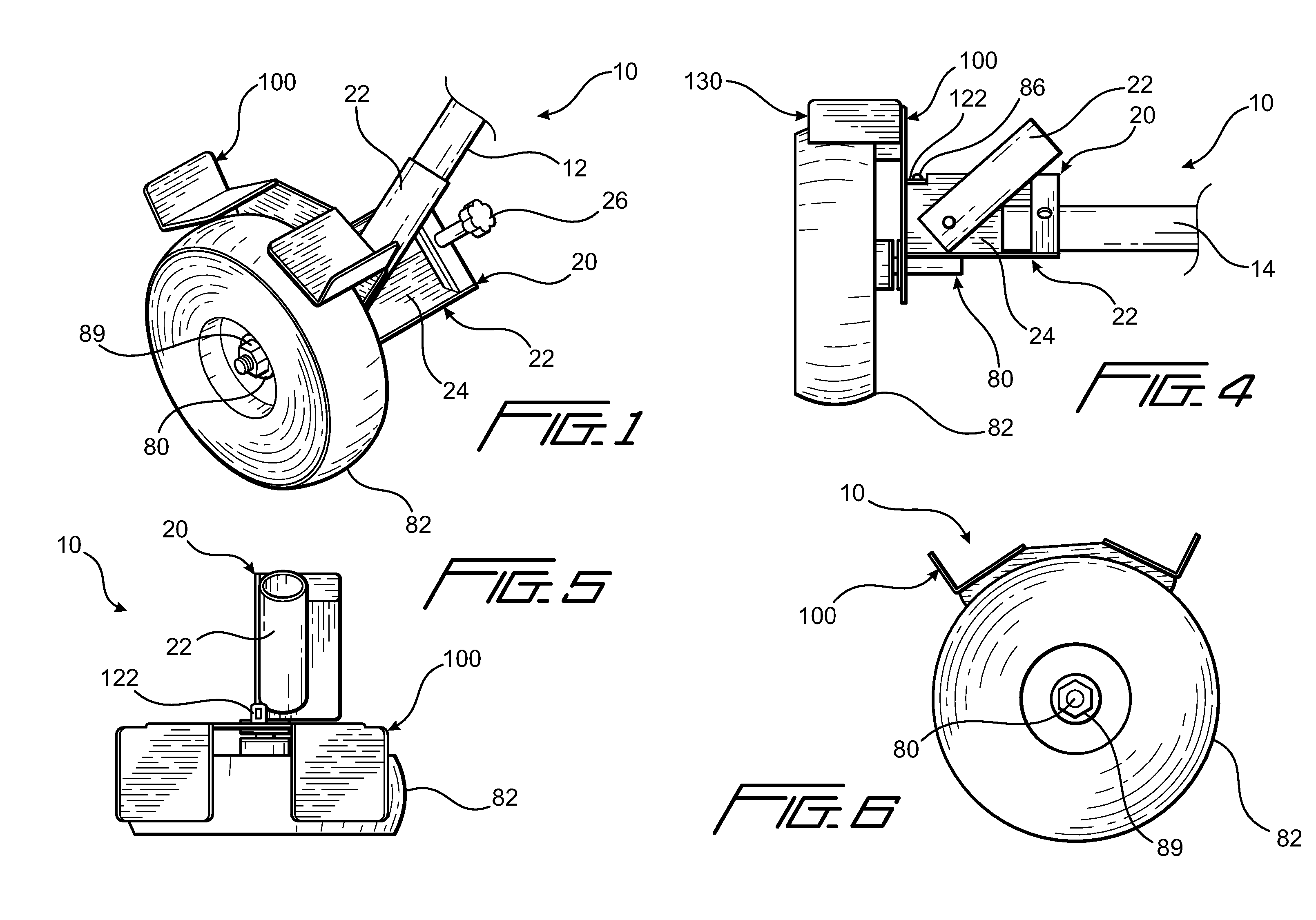
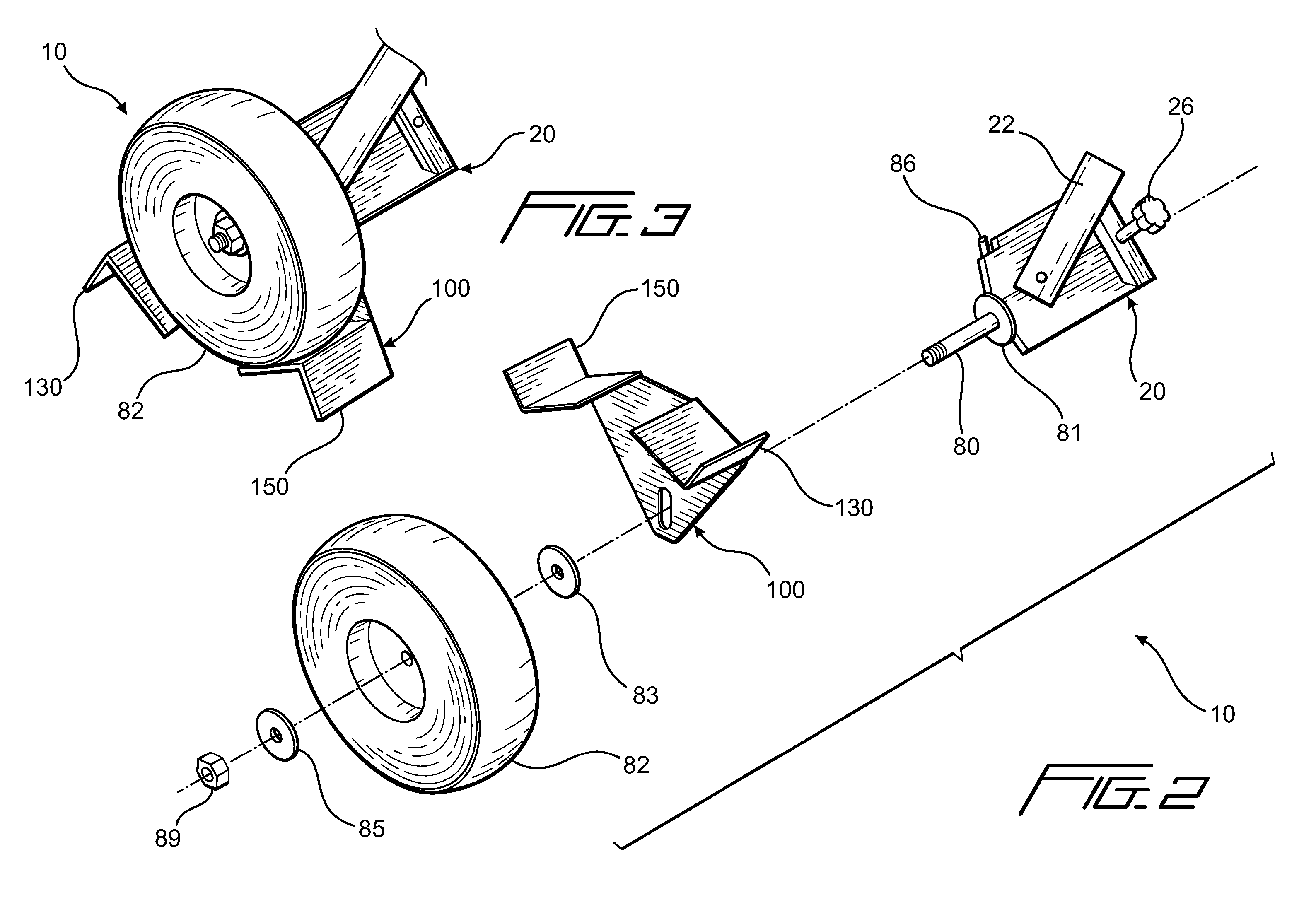
[0029] The present invention provides a device 10 having an first member or axle housing 20 and a second member or chock member 100, as shown in FIG. 1. The device 10 can be removably attached to conventional standing sports equipment, such as, but not limited to pitching machines, L-screens and batting cages.

[0030] The removable wheel caster device 10, as shown in FIGS. 1 through 6 is generally for placement on a piece of equipment that has bottom supports with exposed ends. An example of employment of the device 10 is on L-screens used to protect batting practice pictures in baseball, an extension of a leg 14 is shown in FIG. 2. By attaching the caster 10 to each end of the generally horizontally oriented leg 14 on-the L-screen, one person or user can roll and maneuver the L-screen around a practice field instead...


PUM


Abstract

The present invention is a device for supporting a wheel comprising a first member, which has a retention member and an axle operably configured to receive the wheel, and; a second member, which has a chock and an engagement portion. The second member is rotatably attached to the axle. Further, the second member is operably configured to have an unchocked position when not in use and selectively rotatable to a chocked position against the wheel to keep the wheel from rotating in at least one of a forward and reverse direction when the second member is use. Additionally, the retention member retains the engagement portion of the second member in the unchocked position when the chock is not in use.

Description

CROSS REFERENCE TO RELATED APPLICATION [0001] This nonprovisional application claims the benefit of Provisional Application No.: 60 / 738,791, filed on Nov. 21, 2005, which is incorporated herein by reference in its entirety and to which priority is claimed.BACKGROUND OF THE INVENTION [0002] 1. Field of Invention [0003] The present invention relates to a chock device incorporated into a removable wheel caster for sports equipment such as, but not limited to, baseball pitching machines, protective screens and the like. [0004] 2. Description of Related Art [0005] Coaches and players use conventional standing sports equipment or baseball devices such as pitching machines, L-screens, batting cages, position protection screens and the like to protect players and coaches during practice. Most of the conventional standing sports equipment devices must be carried or dragged from a storage area to the playing field, because they do not have wheels. [0006] Most of such conventional sports equip...

Claims


Application Information

Patent Timeline
IPC IPC(8): B62B5/04
CPCB62B5/049
Inventor JOHNDREAU, STEVEN S.
Owner JOHNDREAU STEVEN S
Why Eureka
Try Eureka