Digital Refocusing for Wide-Angle Images Using Axial-Cone Cameras

Inactive Publication Date: 2011-12-29
MITSUBISHI ELECTRIC RES LAB INC
View PDF6 Cites 162 Cited by
  • Summary
  • Abstract
  • Description
  • Claims
  • Application Information

AI Technical Summary

Benefits of technology

[0016]The embodiments of our invention provide artistic depth of field effects in wide-angle images, which typically exhibit large depth of field, along with dense wide-field-of-view (FOV) three-dimensional (3D) reconstruction. This requires acquiring rays

Problems solved by technology

Designing a practical solution for wide-angle imaging presents challenges when considering factors such

Method used


Image

  • Digital Refocusing for Wide-Angle Images Using Axial-Cone Cameras
  • Digital Refocusing for Wide-Angle Images Using Axial-Cone Cameras
  • Digital Refocusing for Wide-Angle Images Using Axial-Cone Cameras

Examples


Embodiment Construction

Method and System Overview

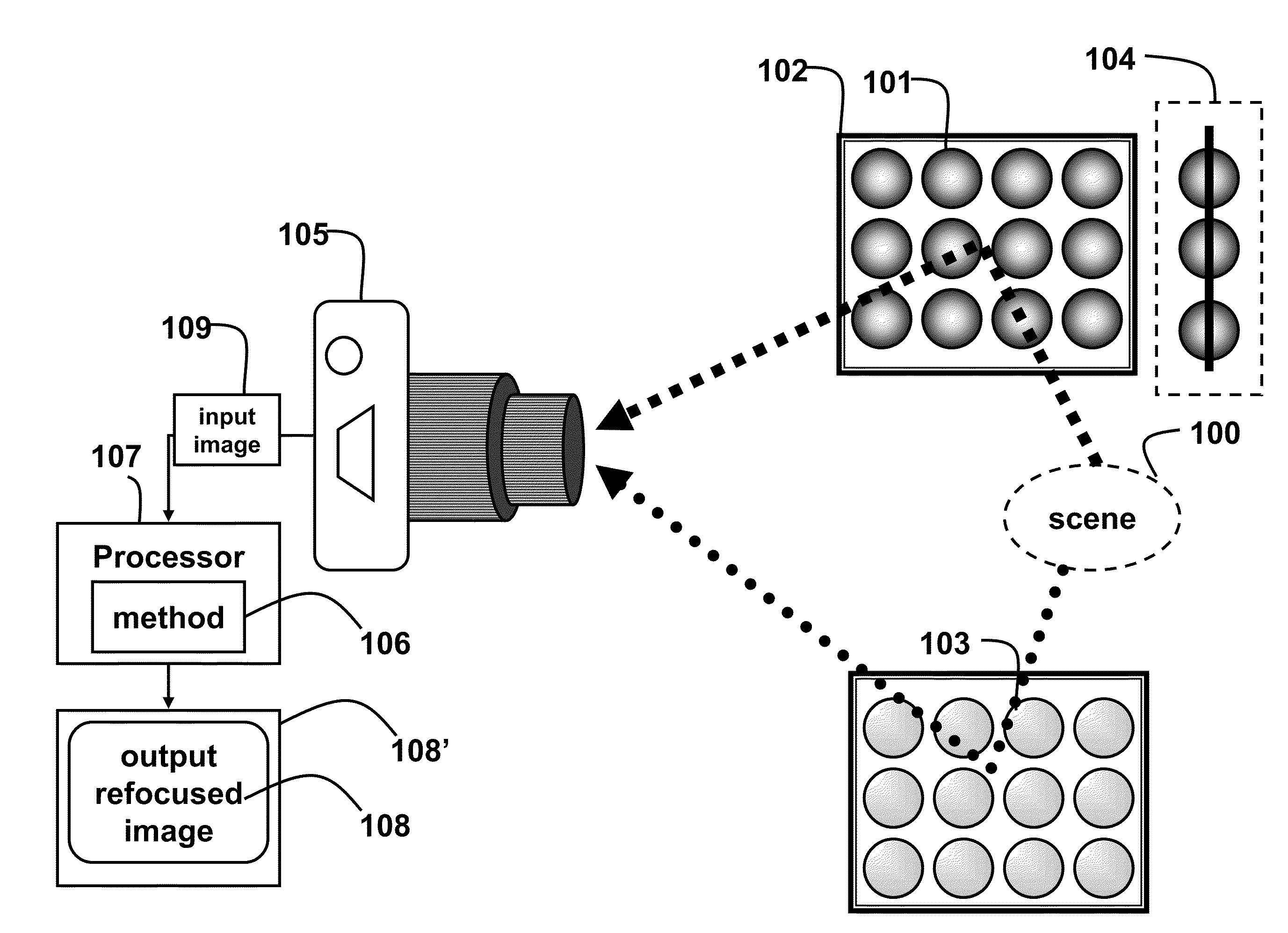
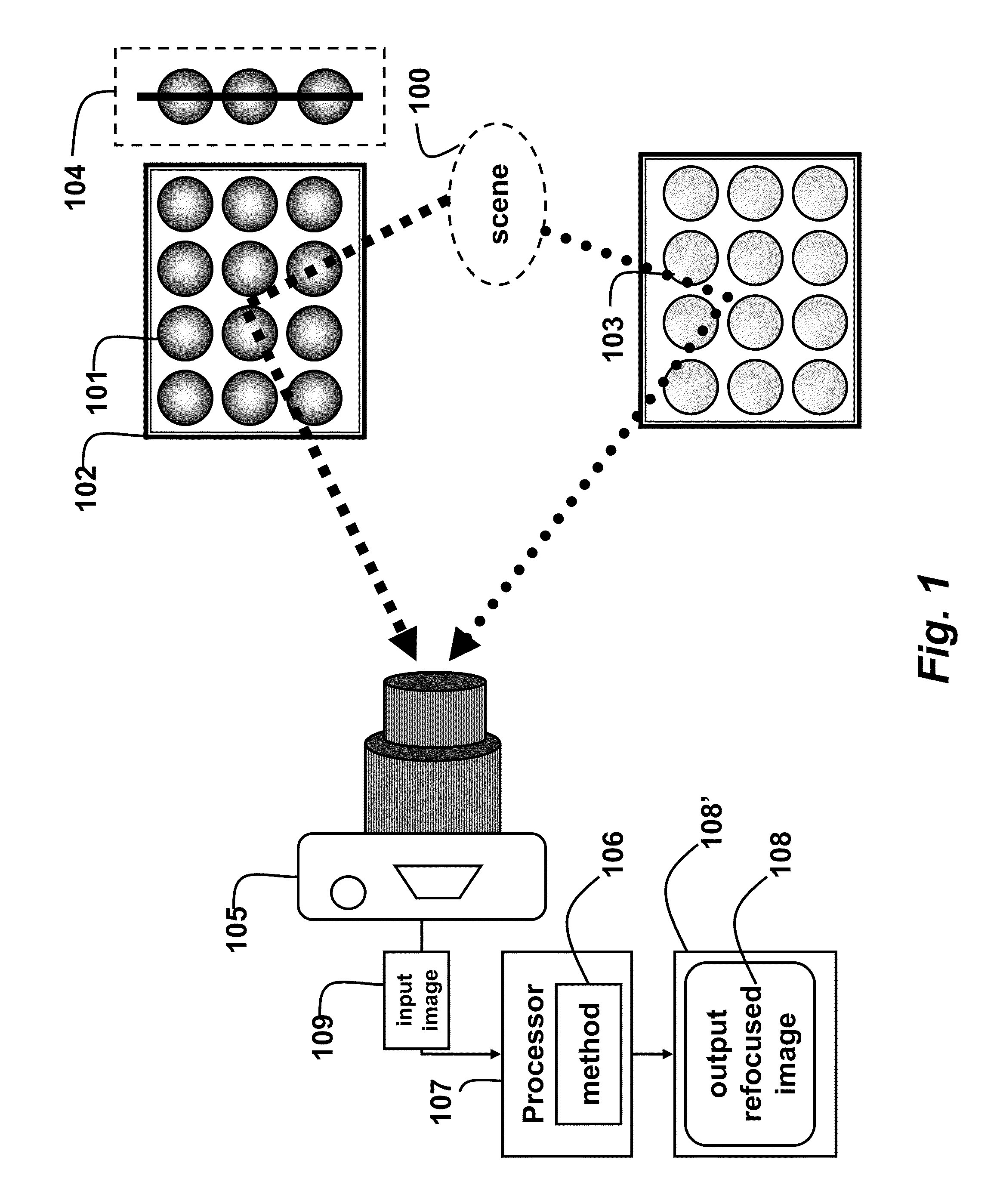
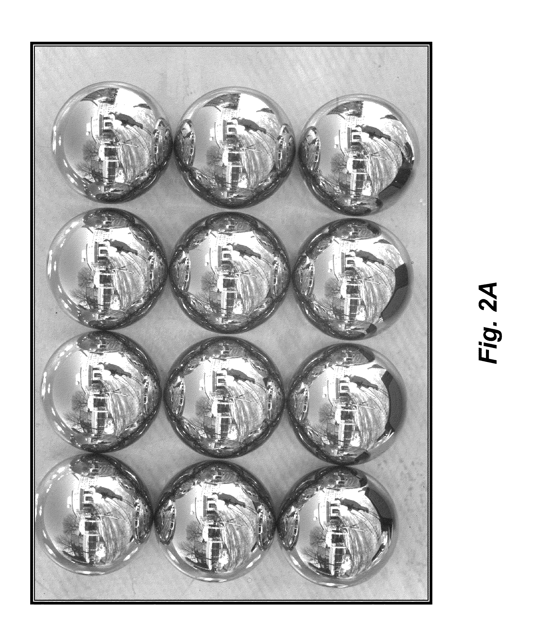
[0028]As shown in FIG. 1, the embodiments of the invention provide a method and system for refocusing for an output image from a single image acquired by a conventional stationary camera with reflective or refractive elements. We can use an array of reflective spheres (e.g., mirror or steel balls) 101 arranged on a planar surface 102 for a reflective setup, or an array of refractive spheres (e.g., glass or acrylic balls) 103 for a refractive setup. By using spheres of different size, our design can be easily scaled to different scene scales. We use an array of spheres of 0.25″ radii for small tabletop scenes, and 0.5″ radii for room-size, or outdoor scenes. Inset 104 shows a side view of the array. The array can be regular, irregular, random, two- or three-dimensional.

[0029]A camera 105 acquires a single input image 109 of a scene 100 as observed in the reflective or refractive spheres. That is, the image shows the scene reflected in each reflective sphere ...


PUM


Abstract

A single camera acquires an input image of a scene as observed in an array of spheres, wherein pixels in the input image corresponding to each sphere form a sphere image. A set of virtual cameras are defined for each sphere on a line joining a center of the sphere and a center of projection of the camera, wherein each virtual camera has a different virtual viewpoint and an associated cone of rays, appearing as a circle of pixels on its virtual image plane. A projective texture mapping of each sphere image is applied to all of the virtual cameras on the virtual image plane to produce a virtual camera image comprising circle of pixels. Each virtual camera image for each sphere is then projected to a refocusing geometry using a refocus viewpoint to produce a wide-angle lightfield view, which are averaged to produce a refocused wide-angle image.

Description

FIELD OF THE INVENTION[0001]This invention relates generally to wide-angle imaging, and more particularly digital refocusing for wide-angle images.BACKGROUND OF THE INVENTION[0002]Wide angle imaging offers a different way to visualize the world. However, typical wide-angle images exhibit large depth of field (DOF). It is desired to provide depth of field effects for wide-angle images.[0003]A conventional method acquires a wide field-of-view (FOV) lightfield using multiple sequential images by a moving camera with a narrow-angle lens or a wide-angle (fish-eye) lens. A translation stage or pan-tilt units can also be used. Wide angle panoramas and mosaics also require multiple images acquired by either rotating the camera around its optical axis, or along a path. These approaches require the scene to be static, and increase the acquisition time. A camera array with wide-angle lenses can avoid these problems. However, this is more expensive and less portable. Moreover, the multiple came...

Claims


Application Information

Patent Timeline
IPC IPC(8): H04N7/00
CPCH04N5/23238G06T2207/10052G06T2200/21G06T5/50H04N23/698
Inventor TAGUCHI, YUICHIAGRAWAL, AMIT K.VEERARAGHAVAN, ASHOK N.RAMALINGAM, SRIKUMARRASKAR, RAMESH
Owner MITSUBISHI ELECTRIC RES LAB INC
Why Eureka
Try Eureka