Optically guided feeding tube, catheters and associated methods

Active Publication Date: 2010-12-02
UNIV OF UTAH RES FOUND
View PDF29 Cites 108 Cited by
  • Summary
  • Abstract
  • Description
  • Claims
  • Application Information

AI Technical Summary

Benefits of technology

[0031]In accordance with still yet another aspect of the present invention, a feeding tube made in accordance with the principles of the present invention may be used as an improved jejunual extension tube in percutaneous gastrojejunal feeding tubes (PEGJ). The feeding tube provides direct visualization for advancement, placement and confirmation of placement in the small bowel, rather than using a guidewire and fluoroscopy or an endoscope to place the jejunal extension tube. With the optical system and steering, a feeding tube made in accordance with the present invention can perform the same task as conventional jejuna feeding tubes without the drawbacks of using endoscopy or fluoroscopy as noted previously.
[0032]In accordance

Problems solved by technology

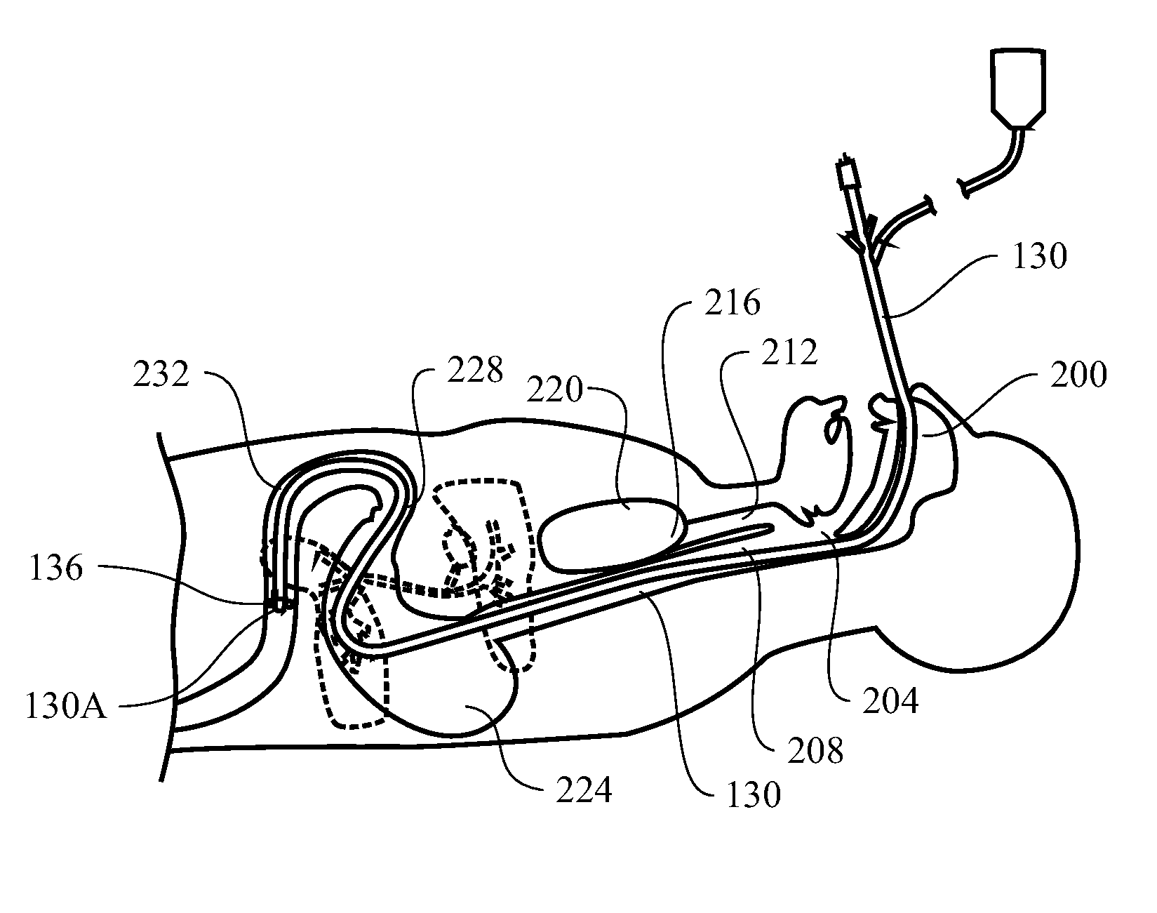
Because the nurse or other hospital staff cannot see the distal end of the feeding tube during advancement, the feeding tube can be incorrectly positioned during the process.
More commonly, misplacement of the feeding tube results in other serious complications including lung placement or puncture or esophageal puncture.
Additionally, providing any feeding solution through the feeding tube into the lungs results in pneumonia with increased morbidity and mortality.
Unfortunately, many common methods for during so leave patients at substantial risk.
However, these tests only attempt to confirm position after placement when complications may have already occurred.
Moreover, X-ray or fluoroscopic confirmation does not clearly confirm placement in the small bowel rather than the stomach.
Additionally, some of these techniques have additional limitations and drawbacks.
For example, fluoroscopic exams and X-Ray verification can cost $400 or more and can expose the patient and the practitioner to harmful radiation.
If a patient is pregnant, or a child, exposure to such radiation is highly undesirable.
Additionally, the use of such verification procedures significantly prolongs the period of time that a patient must wait after a feeding tube is placed before feeding can begin.
If the tube is placed improperly, the wait to begin feeding can take even longer as the process must be repeated.
During this time, the patient is unable to obtain nourishment and any medications which may be delivered via a feeding tube.
Another complication which is common with patie

Method used


Image

  • Optically guided feeding tube, catheters and associated methods
  • Optically guided feeding tube, catheters and associated methods
  • Optically guided feeding tube, catheters and associated methods

Examples


Embodiment Construction

Definitions

[0057]Before the present invention is disclosed and described, it is to be understood that this invention is not limited to the particular structures, process steps, or materials disclosed herein, but is extended to equivalents thereof as would be recognized by those ordinarily skilled in the relevant arts and by the terms set forth in the claims. It should also be understood that terminology employed herein is used for the purpose of describing particular aspects of the invention only and is not intended to limit the invention to the aspects or embodiments shown.

[0058]It must be noted that, as used in this specification and the appended claims, the singular forms “a,”“an,” and “the” may include plural referents unless the context clearly dictates otherwise. Thus, for example, reference to “an optical fiber” may include one or more of such optical fibers, and reference to “the lens” may include reference to one or more of such lenses.

[0059]As used herein, “subject” or “pa...


PUM


Abstract

The present invention provides devices and methods for safe, easy and cost effective means of placing and verifying proper placement of nasogastric and nasoenteric feeding tubes. Specifically, an integrated feeding device including a tube operable to deliver a nutritional and/or medicinal substance to the gastrointestinal tract, an optical system including a light source, flexible optical fibers or a camera, and a lens, and a steering system is disclosed. The components of the system, namely the optical system and the steering system, may be integrated into the tube.

Description

RELATED APPLICATIONS[0001]The present application claims the benefit of U.S. Provisional Patent Application No. 61 / 168,144, filed Apr. 9, 2009, which is expressly incorporated herein in its entirety.FIELD OF THE INVENTION[0002]The present invention relates to devices and methods associated with feeding tubes and other catheters which enable directed placement and confirmation of correct placement using optics to view the interior anatomy of the gastrointestinal tract. In some aspects, the invention relates to nasogastric, nasoenteric and percutaneous feeding tubes and the placement of such tubes. In other aspects, the present invention relates to catheters for drainage and / or removal of fluids. Accordingly, the present invention involves the fields of biology, physics, material science, and engineering.BACKGROUND[0003]Nasogastric and nasoenteric feeding tubes play a crucial role in treating patients having a compromised oral intake. Placement of these feeding tubes is routinely perf...

Claims


Application Information

Patent Timeline
IPC IPC(8): A61B1/04A61M39/00A61M25/10A61F2/958
CPCA61B1/042A61J15/0007A61B1/2733A61B1/2736A61J15/0015A61M25/01A61M25/0147A61J15/0003A61J15/0046A61J15/0049A61J15/0069A61J15/0073A61B1/04A61B1/015A61B1/00165A61B1/00082A61B1/00045A61B1/07A61B1/273A61B1/06
Inventor FANG, JOHNADAMS, MARKMCCREEDY, DYLANNIEMAN, TIMGALLANO, OMARRICHINS, BRETTANDRUS, SHAWN
Owner UNIV OF UTAH RES FOUND
Why Eureka
Try Eureka