Distraction and retraction assembly incorporating locking feature

Pending Publication Date: 2021-05-06
RETROSPINE
View PDF2 Cites 0 Cited by
  • Summary
  • Abstract
  • Description
  • Claims
  • Application Information

AI Technical Summary

Benefits of technology

[0028]Preferably, each side arm of said first pair of side opposing arms comprises a bridge which receives an anchorage pin via at least one recess. The second of said first pair of opposing side arms also includes at least one recess which receives another anchorage pin. Once the vertebral bones have been distracted into the desired position, the locking mechanism allows the anchorage assembly to be secured in a selected position. The present invention has numerous advantages over the prior art including ease of placement of the frame, increased capability of adjustment and increased potential for lordotic a

Problems solved by technology

The prior art distracter assemblies have mechanisms to secure the distracter in a set position but these mechanisms generally lie outside the patients wound and inhibit access to the operating site.
Since the prior art locking mechanisms for distracters are located outside the wound, this increases the transmission distance for locking forces required at the operating site due to a longer moment arm.
This does not provide optimal load transfer to the spinal vertebrae where distraction is required but rather applies the load at a moment arm distant from the required load application site.
The disadvantages of these techniques includes the

Method used


Image

  • Distraction and retraction  assembly incorporating locking feature
  • Distraction and retraction  assembly incorporating locking feature
  • Distraction and retraction  assembly incorporating locking feature

Examples


Embodiment Construction

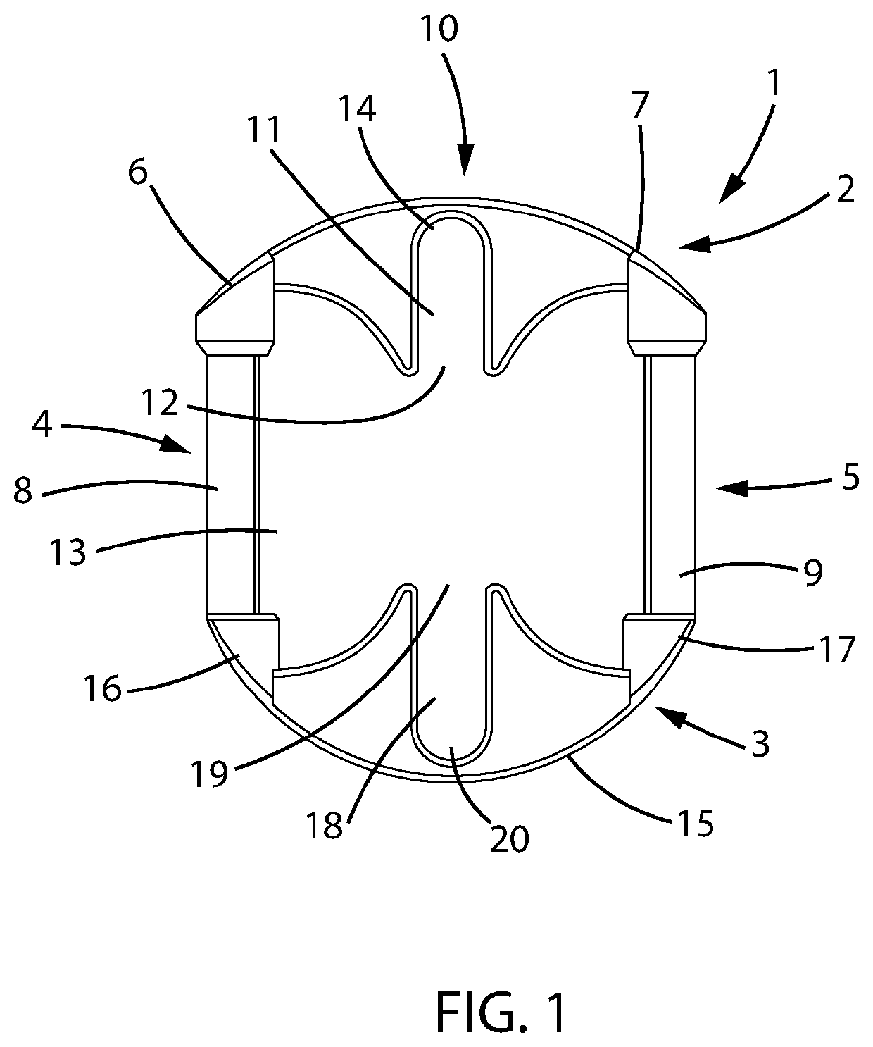
[0039]FIG. 1 shows an enlarged plan view of a frame device 1 of the lockable distraction assembly according to a preferred embodiment. Frame 1 is in use, anchored to bone to set distraction once engaged with anchor pins to be described below. Frame 1 comprises a first pair of opposing sides 2 and 3 and a second pair of opposing sides 4 and 5 which comprise retractor blade support arms 8 and 9. Side 2 includes a bridge 10 which terminates at first and second abutments 6 and 7 which respectively engage one end of retractor support arms 8 and 9. Bridge 10 further comprises an elongated recess 11 having one end 12 open to internal space 13 and a closed end 14 which provides when frame 1 is in use, a limiting abutment for an anchor pin. Side 3 includes a bridge 15 which terminates at first and second abutments 16 and 17 which respectively engage retractor support arms 8 and 9. Bridge 15 further comprises an elongated recess 18 having one end 19 open to internal space 13 and a closed end ...


PUM


Abstract

A device for use in a surgical distraction and retraction assembly, the assembly including the device and at least one bone anchoring pin for securing the device against a bearing surface. The device has an integral frame defining an internal space, the frame having a first pair of opposing side arms and a second pair of opposing side arms. At least one of said side arms of said first pair of opposing side arms including at least one recess each having one of its ends open to the internal space defined by the frame and an opposite closed end terminating within said at least one side arm. Each said recess retains one said at least one bone anchoring pin and is configured to enable relative movement between the frame and the bone anchoring pins. The relative movement allows selective locking of said at least one anchor pin against the frame at a user selected location to maintain a selected extent of vertebral distraction.

Description

BACKGROUND[0001]The present invention relates to bone distraction and retraction assemblies used in bone surgery. More particularly, the invention relates to a distracter locking mechanism and method which enables selection of an extent of bone distraction and locking of the selected distraction. The invention further provides a locking mechanism which allows anchor pins attached to spaced apart vertebrae to be set and maintained at a selected position of distraction by locking of a distraction assembly at a preselected spacing of the vertebrae. More particularly the invention provides a lockable distraction device which also co-operates with retraction arms thereby allowing combined selection and locking of distraction and retraction.PRIOR ART[0002]There are in existence a number of assemblies used in distraction of bone. In particular, there is a variety of known distracters which distract vertebrae during spinal surgery. Such distraction assemblies must be maintained in a setting...

Claims


Application Information

Patent Timeline
IPC IPC(8): A61B17/02A61B17/70
CPCA61B17/025A61B2017/0256A61B17/7076A61B17/0206A61B17/66A61B17/0293A61F2/4611A61B17/8605A61B17/7077
Inventor SEEX, KEVIN
Owner RETROSPINE
Why Eureka
Try Eureka