Suction cup

a technology of suction cups and cups, which is applied in the direction of machine supports, transportation and packaging, and other domestic objects, can solve the problems of unreliability of use, trouble, and relatively complex construction of these cups, and achieve the effect of increasing the suction for

Inactive Publication Date: 2007-05-31
CHANG TA SHUO
View PDF5 Cites 32 Cited by
  • Summary
  • Abstract
  • Description
  • Claims
  • Application Information

AI Technical Summary

Benefits of technology

[0006] It is therefore an object of the present invention to provide a suction cup comprising a resilient plate including a concave bottom and a projecting post having outer threads; a bell including a receptacle on an upper end thereof, a support pivotably secured in the receptacle, a bell body on a lower end thereof, an internal space open to both lateral sides of the bell body, a nut provided in the space, and an internal opening in communication with the space wherein the projecting post passes the opening to threadedly engage with the nut; and a pressing member put on a central portion of the plate around the middle part, the pressing member being disposed inside a bottom of the bell and being in contact with an inner bottom surface of the bell body, the pressing member including an annular member 31 and a plurality of pressing elements formed on a bottom of the annular member 31 whereby placing the suction cup onto a surface and continuously turning the nut will draw both the plate and the bell toward the surface and draw the pressing member onto the plate until a cavity defined by the plate and the surface is decreased to about zero for creating a vacuum to adhere the plate to the surface. By utilizing this suction cup, an increased sucking force is created.

Problems solved by technology

Further, their are relatively complex in constructions, trouble-prone, and unreliable in use.

Method used


Image

  • Suction cup
  • Suction cup
  • Suction cup

Examples


Embodiment Construction

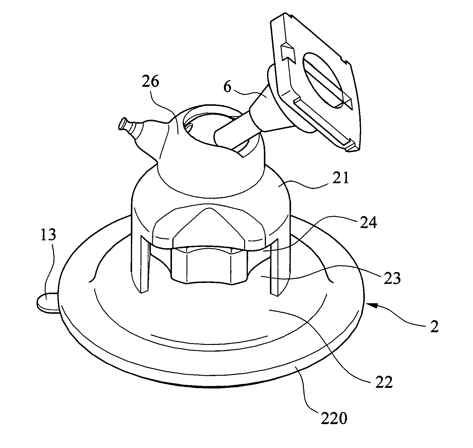
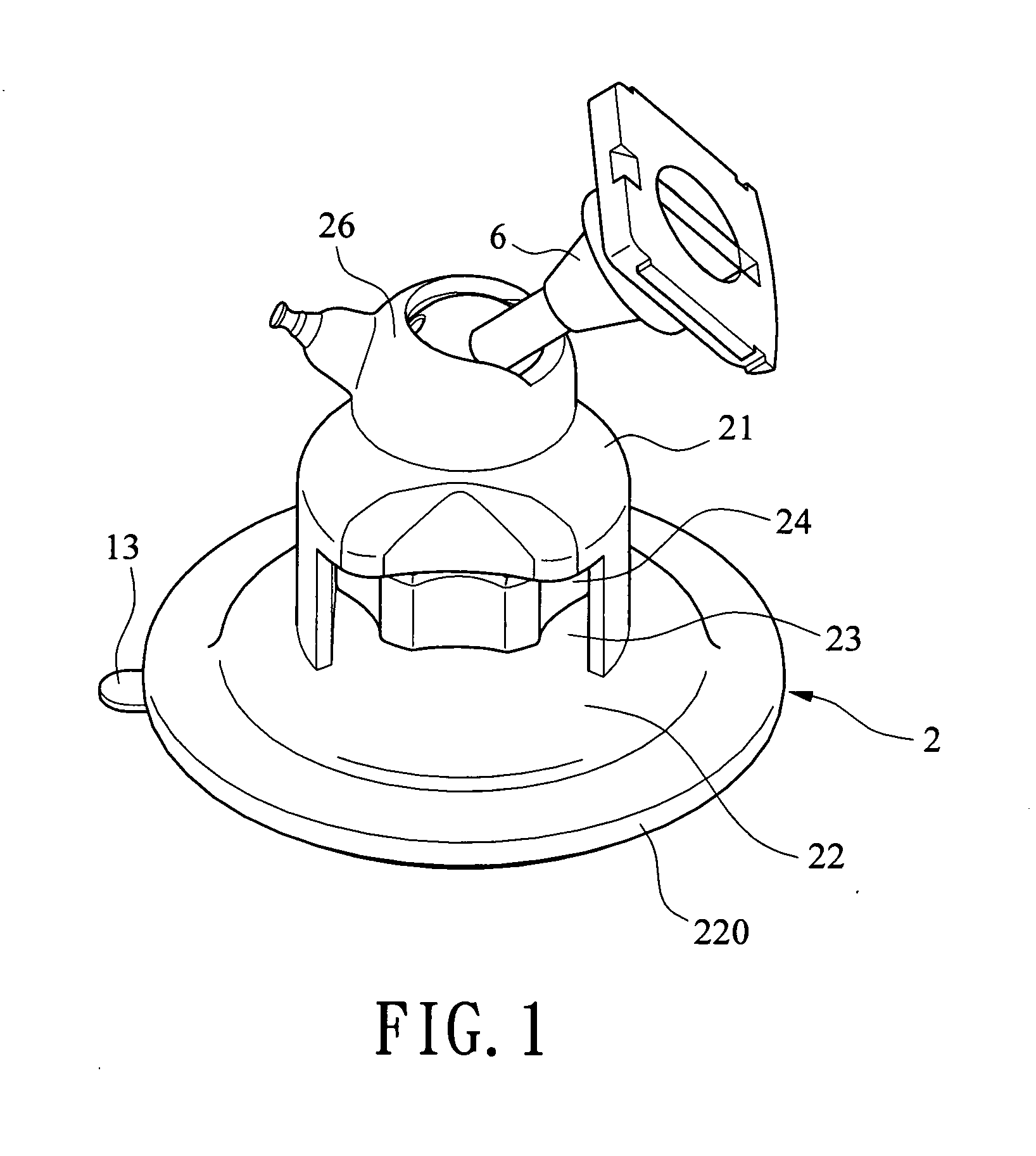
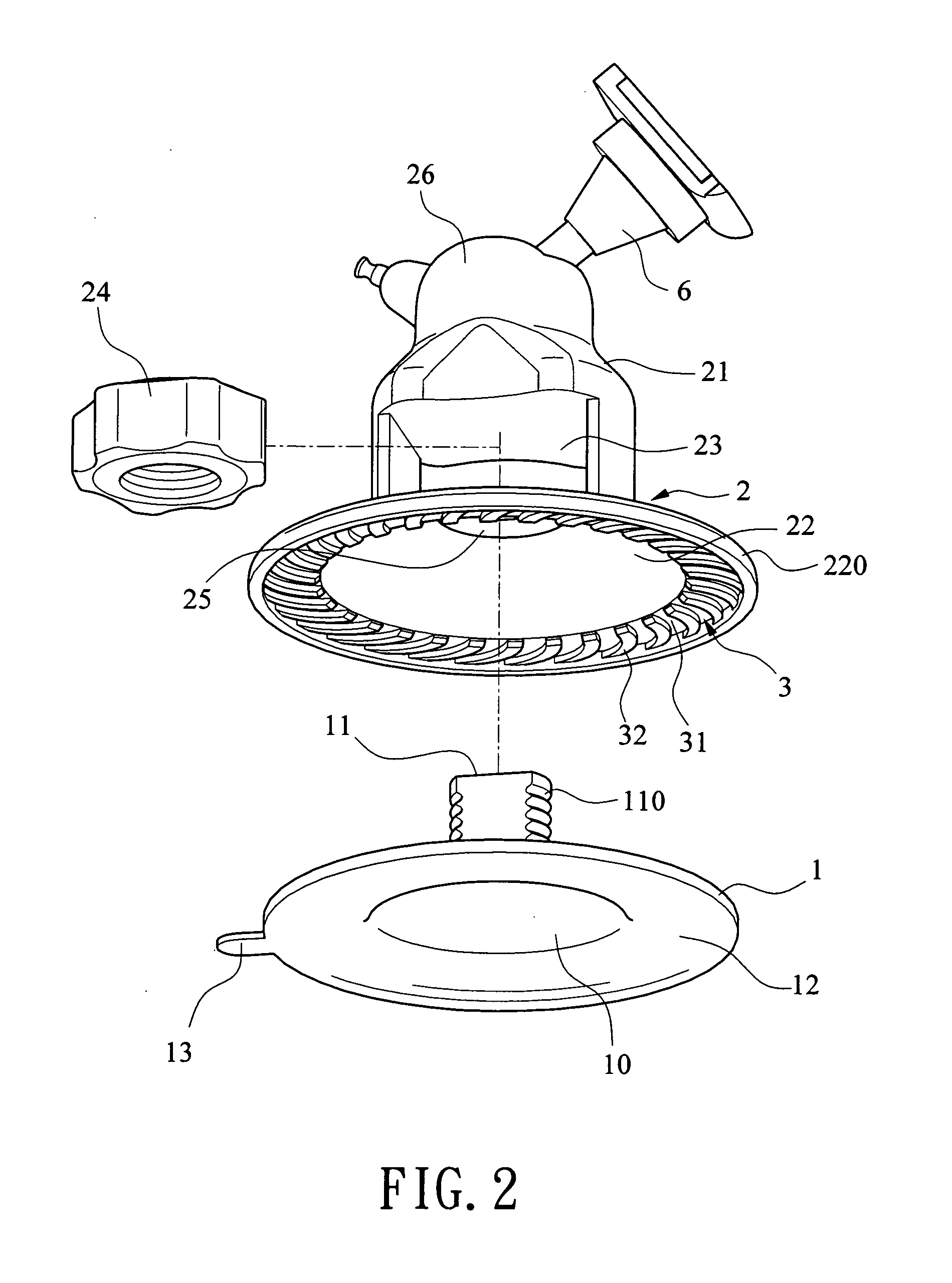
[0019] Referring to FIGS. 1 and 2, a suction cup in accordance with a preferred embodiment of the invention comprises a resilient circular plate 1 formed of soft plastics or rubber, having a slight concave configuration and including a middle projecting post 11 having outer threads 110, a central concave portion 10 on a bottom of the projecting post 11, an annular flat portion 12 on an outer circumferential portion of the concave portion 10, and a tab on an outer portion of the annual flat portion 12; a bell 2 including a main body 21, a spherical receptacle 26 on an upper end of the body 21, a bell member 22 on a lower portion of the body 21, an annular downward flange 220 on a circumference of the bell member 22, an internal space 23 open to both lateral sides of the body 21, a nut 24 provided in the space 23, and an opening 25 disposed on the top of the bell member 22 in communication with the space 23 wherein the projecting post 11 passes the opening 25 to threadedly engage with...


PUM


Abstract

A suction cup includes a resilient plate including a concave bottom and a threaded middle projecting post; a bell including a support pivotably secured in an upper receptacle, an annular flange on a lower end, an internal space open to both lateral sides, a nut in the space threadedly engaged with the middle projecting post; and a pressing member disposed inside bell bottom being in contact with the flange, the pressing member including bottom pressing elements. Placing the suction cup onto a surface and continuously turning the nut will draw both the plate and the bell toward the surface and draw the pressing member onto the plate until a vacuum in a cavity between the plate and the surface is created to adhere the plate to the surface. The pressing elements are ribs or teeth having arcuate or straight shape.

Description

BACKGROUND OF THE INVENTION [0001] 1. Field of Invention [0002] The present invention relates generally to suction devices and more particularly to a suction cup with improved characteristics (e.g., increased sucking force). [0003] 2. Description of Related Art [0004] There have been numerous suggestions in prior patents for suction cups. For example, one of the typical suction cup discloses a suction cup characterized in that a seat is put on the bell, a rubber ring is provided on the seat, a plurality of ribs are extended outward from the ring, and a pressing member is provided under the ribs such that pressing the bell will cause the pressing member to press the suction cup for securely adhering to the surface. Another typical suction cup discloses a suction cup characterized in that a fastening member is provided around the bell, and a threaded member is adapted to drive the bell upward a surface to create a vacuum therebetween so as to adhere to the surface with the additional ...

Claims


Application Information

Patent Timeline
Patent Type & Authority Applications(United States)
IPC IPC(8): F16B47/00
CPCB60R11/02B60R2011/0056B60R2011/0091F16B47/00F16C11/106F16M11/14F16M13/00F16M13/022F16M2200/024
Inventor CHANG, TA SHUO
Owner CHANG TA SHUO
Why Eureka
Try Eureka