Rotary transformer

a transformer and rotor technology, applied in the field of transformers, can solve the problems of affecting the rotational speed of the rotor, and affecting the service life of brushes,

Active Publication Date: 2007-05-31
DUPONT SAFETY & CONSTR INC
View PDF5 Cites 4 Cited by
  • Summary
  • Abstract
  • Description
  • Claims
  • Application Information

AI Technical Summary

Benefits of technology

[0014] The present invention is directed to a rotary transformer for coupling electrical power at a high level into a rotating member operab

Problems solved by technology

This may cause the rotational speed of the rotor to change.
Independently controlling the power delivered to the load in the rotor without affecting the rotational speed of the rotor thus presents practical problems.
The brushes have limited service life due to wear while in use and must be periodically replaced.
At high current levels an

Method used


Image

  • Rotary transformer
  • Rotary transformer
  • Rotary transformer

Examples


Embodiment Construction

[0023] Throughout the following detailed description similar reference characters refer to similar elements in all figures of the drawings.

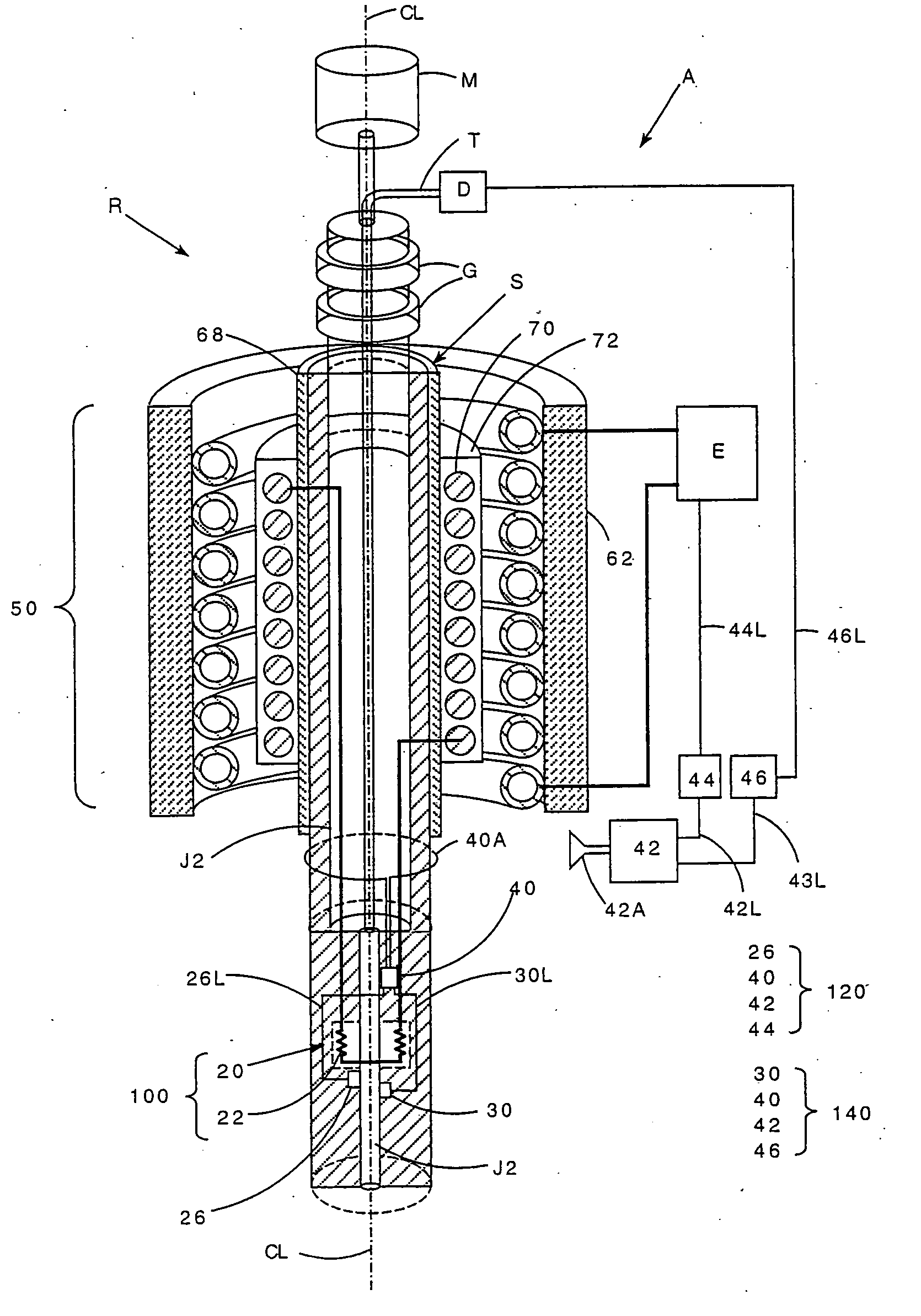
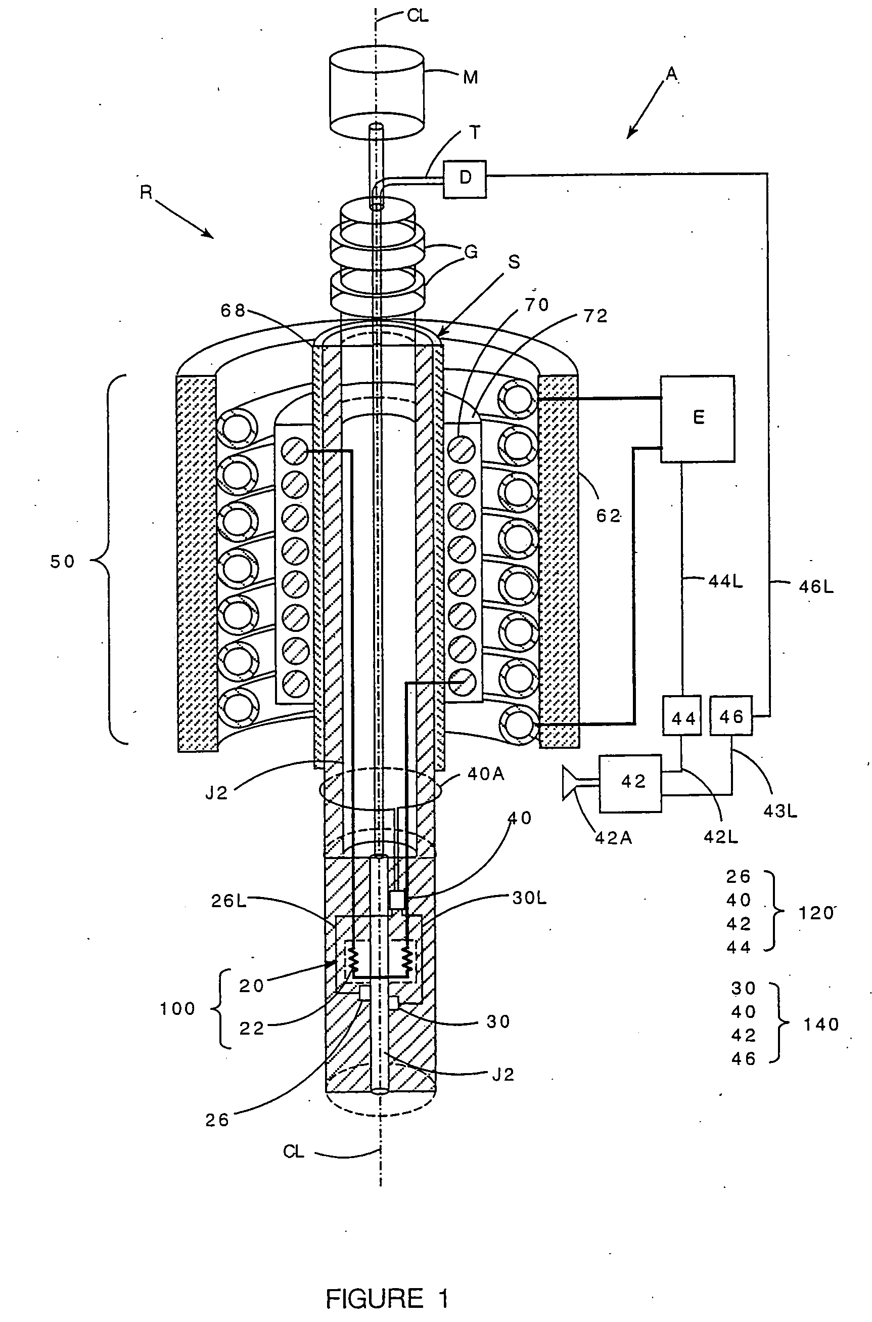
[0024]FIG. 1 is a stylized pictorial representation, partially in section, of a rotary apparatus generally indicated by reference character A. The overall apparatus A includes a rotor R comprising a shaft S. The shaft S has a stepped bore J extending thereof. The bore J includes a larger diameter upper portion J1 and a reduced diameter lower portion J2. A supply tube T extends centrally and axially through the upper portion J1 of the shaft S. The tube T supplies a fluid material at a predetermined regulated flow rate from a pump D into the lower portion J2 of the bore.

[0025] The rotor R is supported by bearings G for rotation about an axis of rotation CL. Motive force for the rotation of the rotor R is provided by a drive motor M.

[0026] The physical properties of the fluid material are influenced by the both its temperature and the pressure. A...


PUM


Abstract

A rotary transformer for coupling electrical power at a high level into a rotor operable at a high rotational speed without the introduction of undesirable electromagnetic torque and problems of dynamic mechanical instability comprises a stationary primary mounted in surrounding relationship with respect to the rotor, an electromagnetic shield having an exterior surface thereon mounted to the rotor, and a secondary mounted on the exterior surface of the shield. The secondary is connected in an electrical circuit with the load such that the application of an alternating current having a frequency of at least one (1) kilohertz to the primary produces an alternating electromagnetic field having flux lines in the secondary in the secondary oriented generally parallel to the axis of rotation. The alternation of the electromagnetic field induces a voltage in the secondary that generates an electric current to the load. The shield isolates the rotor from the alternating electromagnetic field to prevent eddy current heating of the rotor.

Description

CROSS REFERENCE TO RELATED APPLICATIONS [0001] Subject matter disclosed herein may be disclosed in the following applications filed concurrently herewith, all assigned to the assignee of the present invention: [0002]“Heating System and Temperature Control System For A Rotor”, Ser. No. ______, (CL3189 US NA), filed in the names of Edward J. Delawski, Michael R. McQuade and Mehrdad Mehdizadeh; and [0003]“Pressure Control System For A Rotor”, Ser. No. ______, (CL3192US NA), filed in the names of Edward J. Delawski, Michael R. McQuade and Mehrdad Mehdizadeh.BACKGROUND OF THE INVENTION [0004] 1. Field of the Invention [0005] This invention relates to a transformer for transferring electrical power into a machine member that is rotating at high speed. [0006] 2. Description of Related Art [0007] In rotating mechanical systems there is often a need to transfer electrical power into a load mounted on a rotor operating at high rotational speeds. [0008] A common method of power transfer is mag...

Claims


Application Information

Patent Timeline
IPC IPC(8): H01F21/06
CPCH01F27/367H01F38/18H01F27/36H01F27/363
Inventor MEHDIZADEH, MEHRDADFOGGIN, GARY W.
Owner DUPONT SAFETY & CONSTR INC
Why Eureka
Try Eureka