
Sensing system and components for detecting and remotely monitoring carbon monoxide in a space of concern

a carbon monoxide and sensing system technology, applied in the field of co sensing system, can solve the problems of carbon monoxide (co) being odorless, tasteless gas, and carbon monoxide being particularly dangerous,

Active Publication Date: 2007-05-31
GUARDIAN LLC
View PDF13 Cites 28 Cited by
  • Summary
  • Abstract
  • Description
  • Claims
  • Application Information

AI Technical Summary

Problems solved by technology

Carbon monoxide (CO) is an odorless, tasteless gas that often results from incomplete combustion of fuel.
Carbon monoxide can be particularly dangerous when accumulated in a space such as an aircraft cabin, a motor vehicle occupant compartment, a garage, an unventilated room or office, etc.

Method used


Image

  • Sensing system and components for detecting and remotely monitoring carbon monoxide in a space of concern
  • Sensing system and components for detecting and remotely monitoring carbon monoxide in a space of concern
  • Sensing system and components for detecting and remotely monitoring carbon monoxide in a space of concern

Examples


Embodiment Construction

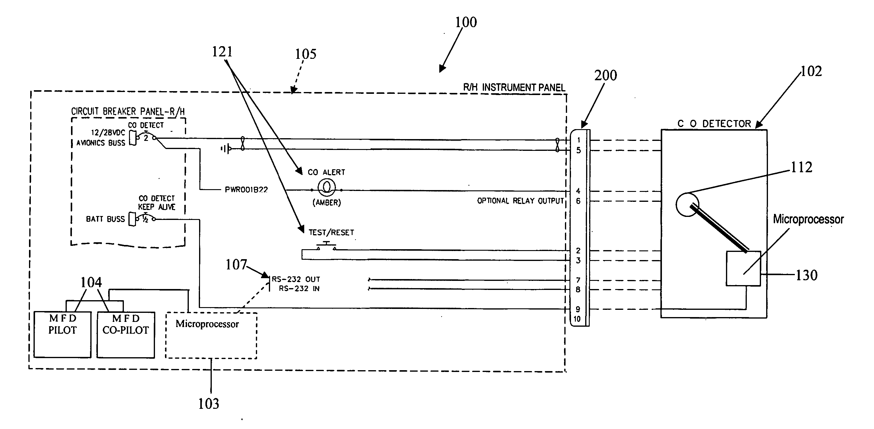
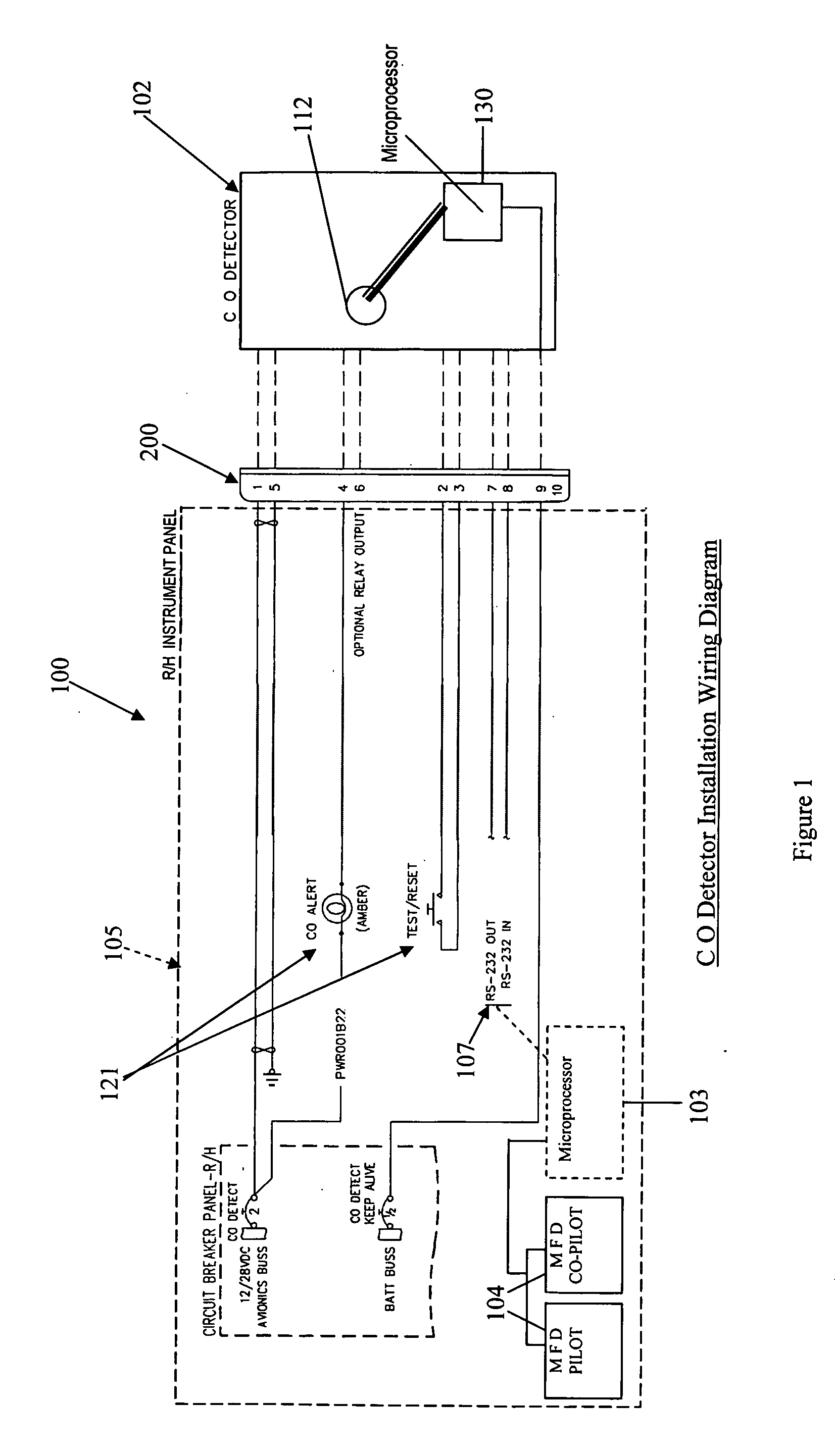
[0020] As discussed above, the present invention relates to a new and useful CO sensing system that is particularly useful in detecting and monitoring CO levels in a space of concern in an aircraft. The principles of the invention are described below primarily in connection with a CO sensing system for an aircraft, but from that description, the manner in which those principles can be applied to CO sensing systems for various applications will become apparent to those in the art.

[0021] Initially, it is believed useful to explain the importance of CO detection in an aircraft, and also the importance of remote communication of CO information to a remote monitoring device, according to the principles of the present invention.

[0022] Carbon monoxide (CO) is an odorless, tasteless gas that often results from incomplete combustion of fuel. Carbon monoxide can be particularly dangerous when accumulated in a space such as an aircraft cabin, a motor vehicle occupant compartment, a cabin or ...


PUM


Abstract

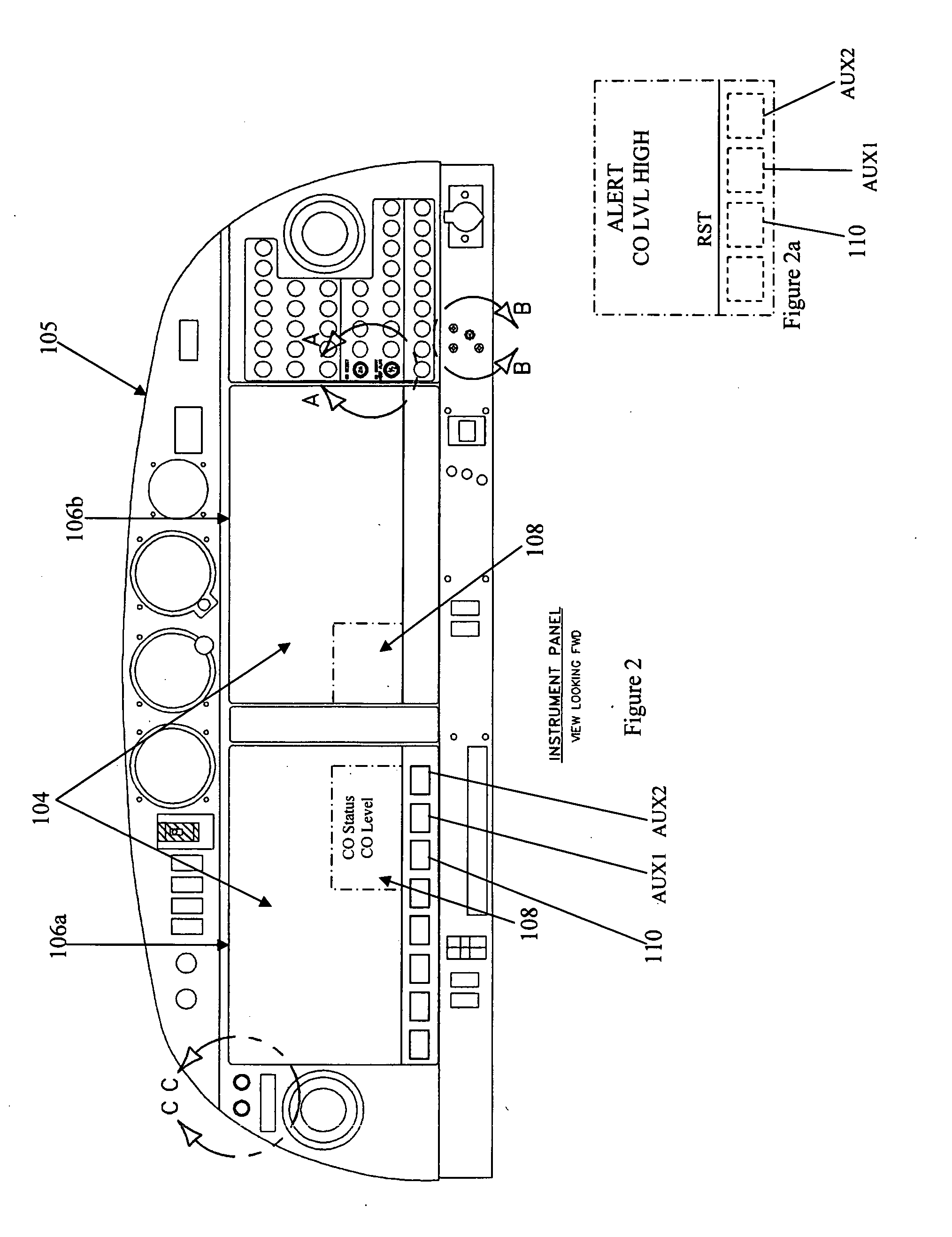
A sensing device for detecting the presence of carbon monoxide in a selected space of concern and communicating with a remote monitoring device is provided. The sensing device comprises (a) a detection device configured to sense the presence of carbon monoxide in the selected space of concern, (b) a monitoring device remote from the detection device, for communicating information to an operator, and (c) the detector in circuit communication with the monitoring device, to transmit information from the detection device to the monitoring device that is related to carbon monoxide in the selected space. According to one preferred embodiment, the sensing device is designed for an aircraft. The remote monitoring device is the multifunctional display of the aircraft cockpit. In addition, in a preferred embodiment, a reset / retest actuator is connected with the multifunctional display, and is in circuit communication with the detection device. The reset / retest actuator is selectively actuated from the multifunctional display to send a reset / retest signal to the detection device, to reset the detection device, and to initiate operation of the detection device to repeat its carbon monoxide detection process and provide a signal related to the level of carbon monoxide detected by the detection device. Moreover, in a preferred embodiment, a heating element is provided that is proximate to the carbon monoxide detection component. The heating element is selectively actuated to heat the air space about the carbon monoxide detection component. Also, an adjustment device associated with the output of the CO detection device, for adjusting the output of the detection device in response to a signal related to the air pressure in the selected space of concern. These features are particularly useful in a detection device for an aircraft, where ambient temperatures may drop to levels that can adversely affect the performance of the detection device, or where pressure changes in the aircraft may affect the sensitivity of the detection device.

Description

BACKGROUND [0001] The present invention relates to a new and useful CO sensing system, and components of such a system, for detecting and remotely monitoring carbon monoxide (CO) in a space of concern. [0002] Carbon monoxide (CO) is an odorless, tasteless gas that often results from incomplete combustion of fuel. Carbon monoxide can be particularly dangerous when accumulated in a space such as an aircraft cabin, a motor vehicle occupant compartment, a garage, an unventilated room or office, etc. [0003] CO detectors are generally intended to identify when CO levels in a space of concern reach dangerous levels (e.g. 50 ppm). In applicant's experience, prior CO detectors are designed to emit visual and / or audio alarms that alert an occupant of the space that the CO level is dangerous. Such detectors are usually in the form of detection boxes that provide a visual alarm or audio signal to those in the vicinity of the detection box. SUMMARY OF THE INVENTION [0004] The present invention i...

Claims


Application Information

Patent Timeline
Patent Type & Authority Applications(United States)
IPC IPC(8): G08B17/10
CPCG08B21/14
Inventor VIJ, ASHOK K.
Owner GUARDIAN LLC
Learn More