
Inkjet image forming apparatus having a capping unit

a technology of capping unit and image forming apparatus, which is applied in the direction of printing, other printing apparatus, etc., can solve the problem of contamination of the inside of the image forming apparatus

Inactive Publication Date: 2007-06-07
S PRINTING SOLUTION CO LTD
View PDF4 Cites 15 Cited by
  • Summary
  • Abstract
  • Description
  • Claims
  • Application Information

AI Technical Summary

Benefits of technology

[0006] The present general inventive concept provides an inkjet image forming apparatus employing an array inkjet head that can be prevented from being contaminated by particles occurring due to preliminary spitting, and a preliminary spitting method thereof.
[0009] The nozzle unit may include a plurality of head chips each having a plurality of nozzles, and the spitting hole of the cap member may be formed in plural to correspond to the respective head chips. The cap member may include an outer wall completely enclosing the nozzle unit and an inner wall formed along an edge of the plurality of spitting holes. The capping unit further may include an elastic member providing the cap member with an elastic force in a direction to contact the nozzle unit. The capping unit further may include a cap plate to evenly support the cap member.

Problems solved by technology

In the case of the array type inkjet head, the fog of ink may be generated so much, which may contaminate an inside of the image forming apparatus.

Method used


Image

  • Inkjet image forming apparatus having a capping unit
  • Inkjet image forming apparatus having a capping unit
  • Inkjet image forming apparatus having a capping unit

Examples


Embodiment Construction

[0027] Reference will now be made in detail to the embodiments of the present general inventive concept, examples of which are illustrated in the accompanying drawings, wherein like reference numerals refer to the like elements throughout. The embodiments are described below in order to explain the present general inventive concept by referring to the figures.

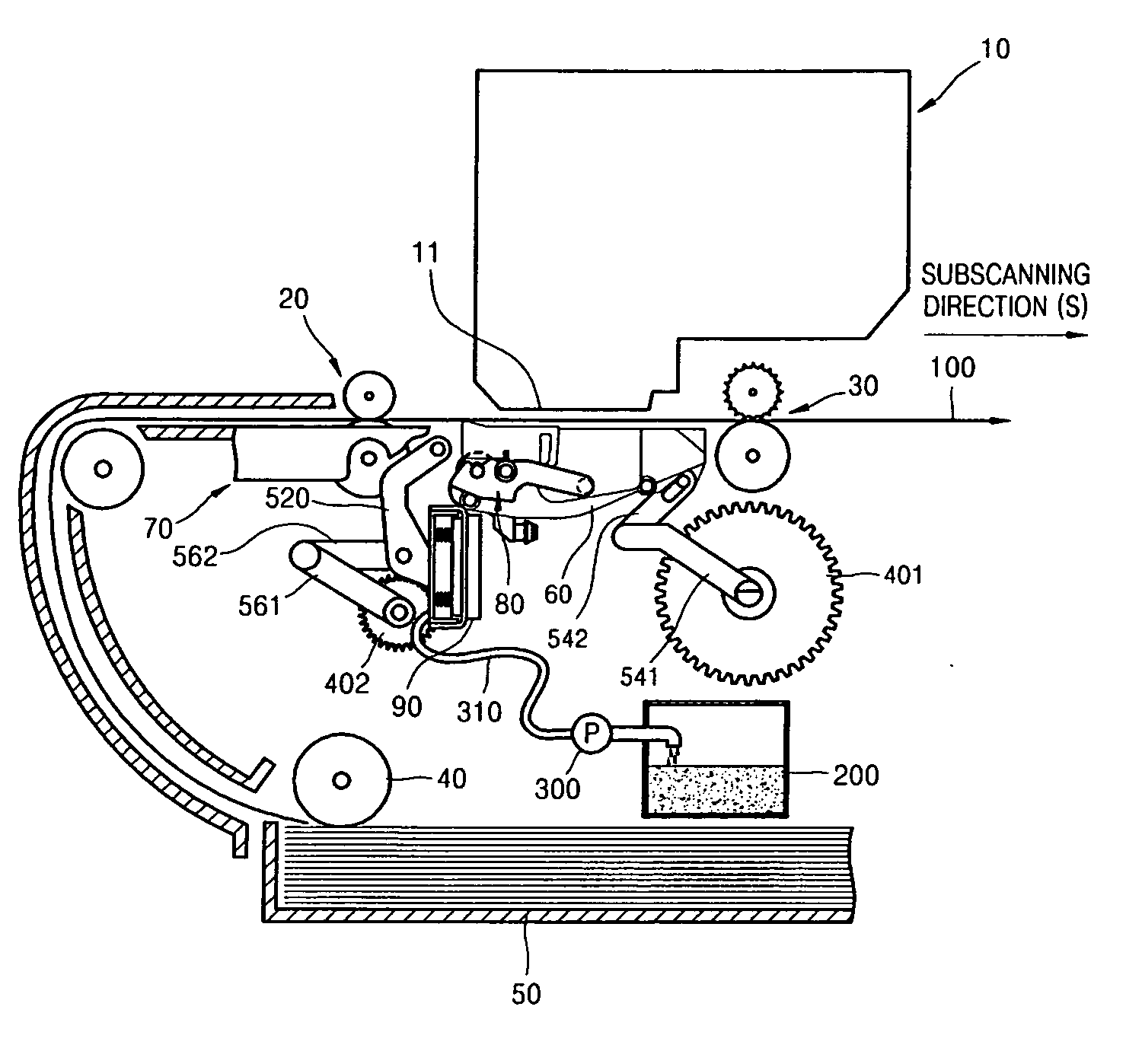
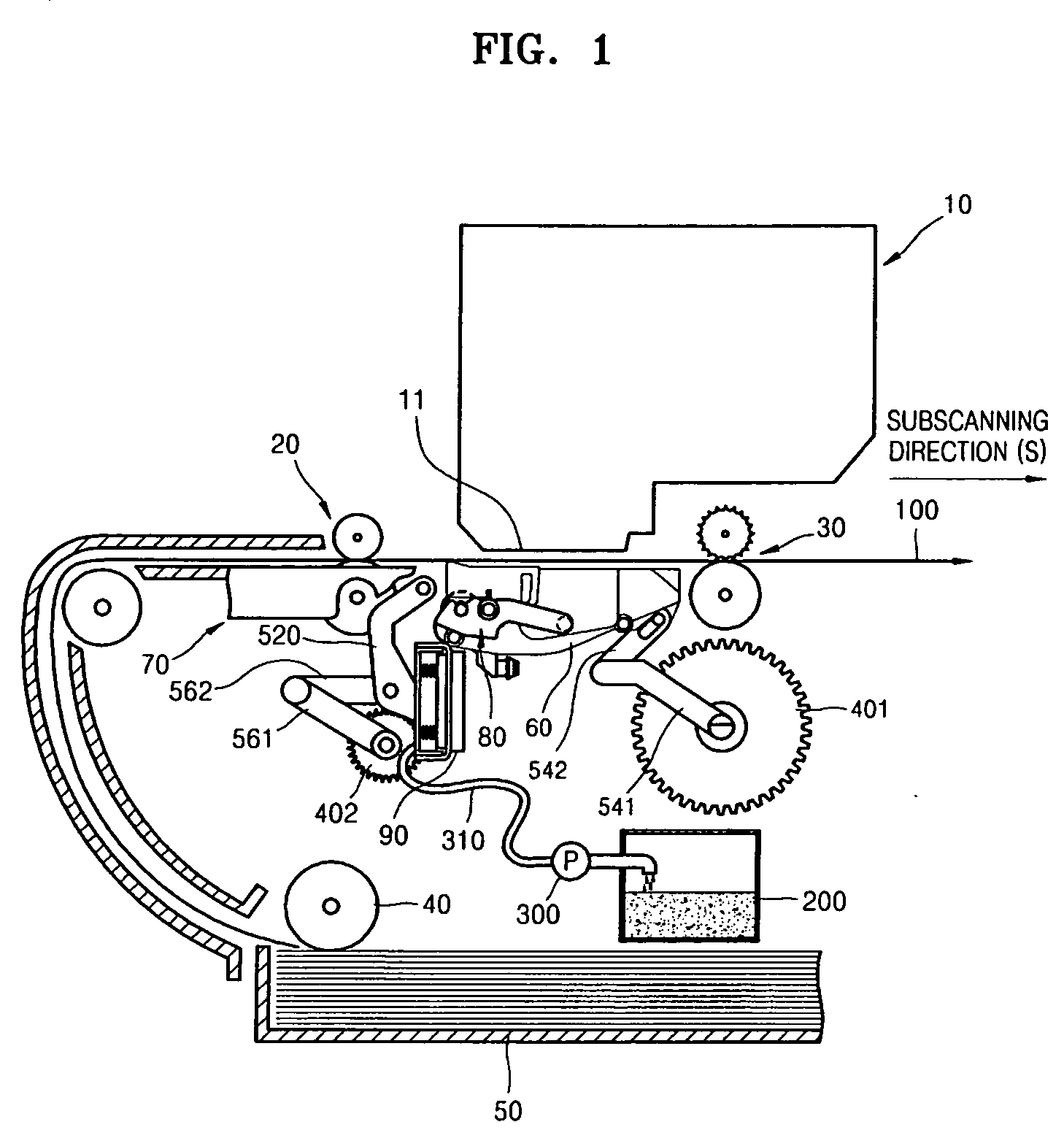
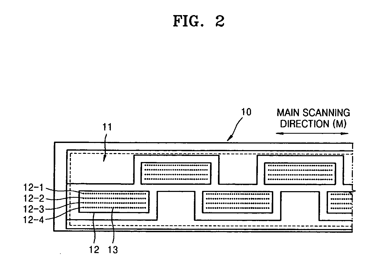
[0028]FIG. 1 is a schematic view illustrating an inkjet image forming apparatus employing an array type inkjet head according to an embodiment of the present general inventive concept. Referring to FIG. 1, a printing medium, such as a sheet of paper 100, picked up by a pickup roller 40 from a feeder cassette 50 is transferred in a subscanning direction ‘S’ by a transfer unit 20. An inkjet head 10 is disposed above the paper 100. The inkjet head 10 has a nozzle unit 11 having a length corresponding to a width of the paper 100 in a main scanning direction ‘M’, and is an array type inkjet head to spray ink onto the paper 100 at a...


PUM


Abstract

An inkjet image forming apparatus includes an inkjet head having a nozzle unit having a length in a main scanning direction corresponding to a width of a printing medium, a capping unit to move to a capping position to cap the nozzle unit and an uncapping position for a printing. The capping unit includes a cap member having a spitting hole and covering the nozzle unit, an absorbing member to absorb an ink passing through the spitting hole, and a support member disposed at a position where the cap member and the absorbing member are installed, the support member receiving the ink spitted.

Description

CROSS-REFERENCE TO RELATED APPLICATIONS [0001] This application claims priority under 35 U.S.C. §119(a) from Korean Patent Application No. 10-2005-0116893, filed on Dec. 2, 2005, in the Korean Intellectual Property Office, the disclosure of which is incorporated herein in its entirety by reference. BACKGROUND OF THE INVENTION [0002] 1. Field of the Invention [0003] The present general inventive concept relates to an inkjet image forming apparatus and a maintenance method thereof, and more particularly, to an inkjet image forming apparatus employing an array inkjet head having a nozzle unit having a length corresponding to a width of a printing medium in a main scanning direction, and a preliminary spitting method thereof. [0004] 2. Description of the Related Art [0005] Inkjet image forming apparatuses form an image by firing ink from an inkjet head (e.g., shuttle type inkjet head) onto a sheet of paper while reciprocating the inkjet head in a main scanning direction and feeding the ...

Claims


Application Information

Patent Timeline
IPC IPC(8): B41J2/165
CPCB41J2/16508B41J2/16526B41J2/16585B41J2/1721B41J11/20B41J2/165B41J2/16502
Inventor HA, DONG-WOO
Owner S PRINTING SOLUTION CO LTD
Learn More