

Pyrotechnic safety device of reduced dimensions
a safety device and pyrotechnic technology, applied in the direction of ammunition fuzes, weapons, weapon components, etc., can solve the problems of reducing the reliability of arming, encumbering them, and deteriorating mechanical properties
- Summary
- Abstract
- Description
- Claims
- Application Information
AI Technical Summary
Benefits of technology
Problems solved by technology
Method used
Image

Examples
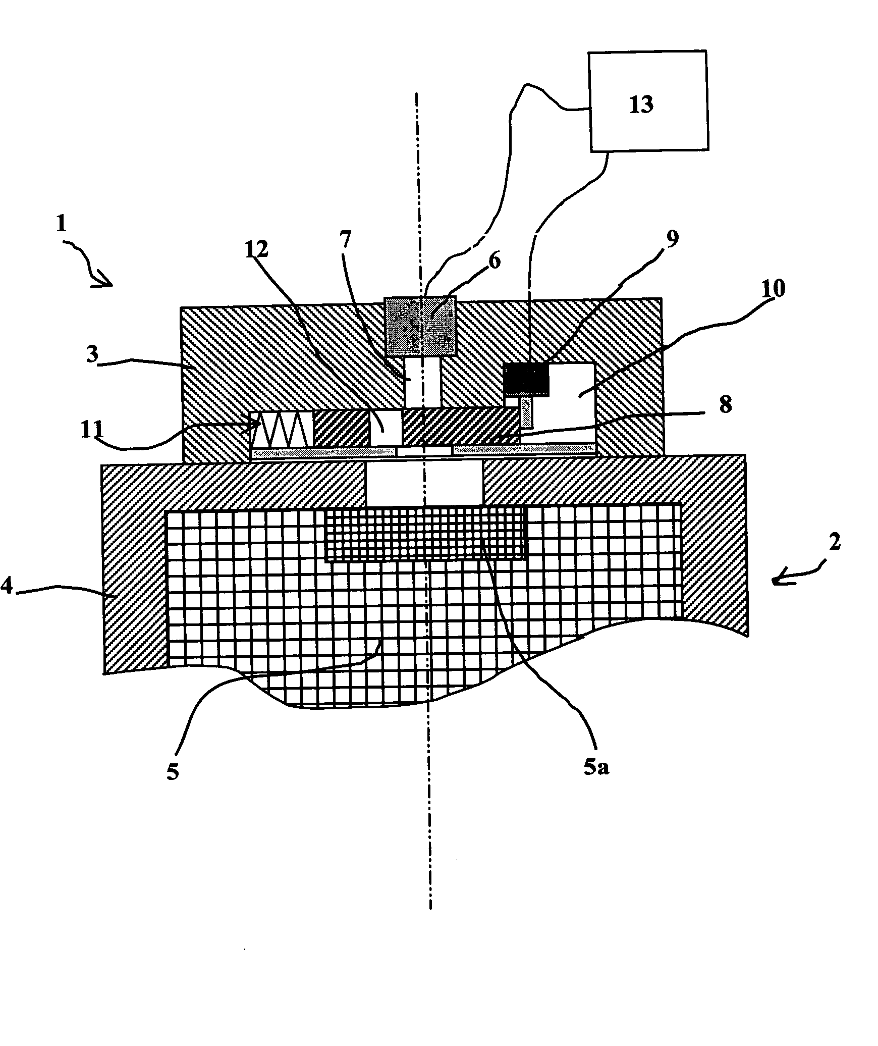
first embodiment
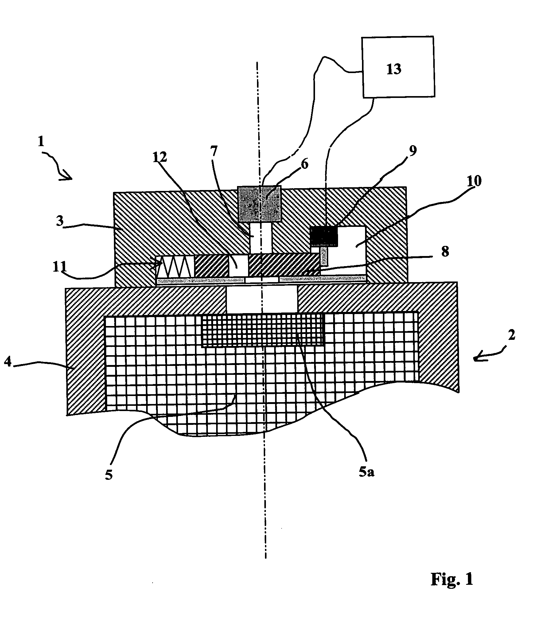
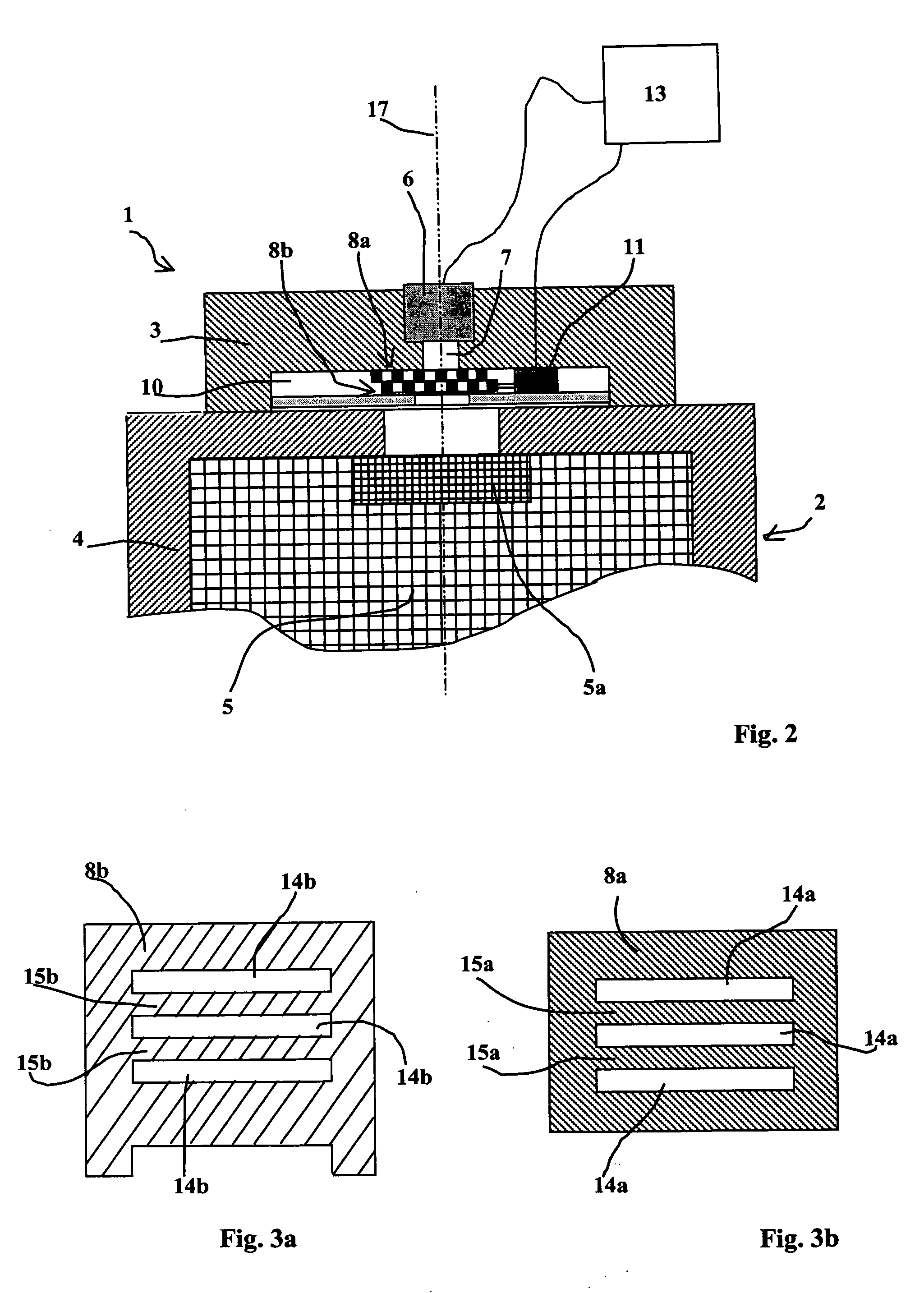
[0050]FIG. 2 thus shows the invention in which the barrier 8 incorporates two elements 8a and 8b which are positioned on top of one another opposite the transmission channel 7.
[0051] Element 8a is immobile (for example bonded to a bottom wall of the housing 10) whereas element 8b is mobile and is displaced by motor means 11 which here are a micro motor activated by the control means 13.
[0052] Naturally, the motor means may be replaced by a spring and a lock may be provided which would be released by the control means 13.
[0053] According to an important characteristic of this embodiment, each element 8a and 8b of the barrier incorporates slots 14a or 14b which are separated by tongues 15a or 15b.
[0054] Elements 8a and 8b may be seen more particularly in FIGS. 3a and 3b. Slots 14a and 14b of each element 8a and 8b are of substantially the same dimensions. Tongues 15a and 15b are of substantially the same dimensions as the slots.
[0055]FIGS. 4a and 4b make it easier to understand th...
second embodiment
[0070]FIGS. 5 and 6 partially show a safety device according to the invention.
[0071] This device is shown as a cross section and the transmission channel 7 appears in FIG. 5 in the shape of a circle of dotted lines.
[0072] The barrier 8 is here constituted by four sectors of cylinders each of 90°: 8a, 8b, 8c, 8d. These sectors are each delimited by orthogonal planes 16.
[0073] Each sector 8a, 8b, 8c, 8d may be radially displaced by motor means 11a, 11b, 11c or 11d.
[0074] The device is shown in FIG. 5 in its safety position in which the four sectors are joined two by two and fully block the transmission channel 7. The elements are in mutual contact by contact surfaces 16 which here are planes 16ab, 16ad, . . . 16cb (cf. FIG. 6).
[0075] When the elements are in the safety position, the different planes 16 are in contact in a zone positioned opposite the transmission channel7.
[0076] We can see in FIG. 5 that these planes form a cross centered on the transmission channel 7.
[0077] The...
third embodiment
[0086]FIGS. 7 and 8 show the invention.
[0087] In this embodiment, the barrier 8 is constituted by two elements 8a and 8b which are able to be displaced radially with respect to the transmission channel 7.
[0088] Elements 8a and 8b here are substantially parallelepipedic in shape and their thickness is greater than or equal to the diameter of the channel 7.
[0089] Each element 8a, 8b can be displaced by motor means 11a, 11b (here, electric micro motors connected to the control means 13).
[0090] In place of the micro motors 11 spring means may naturally be implemented and blocking devices may be used which would be activated by the control means 13.
[0091] Once again, when the device is in its safety position, elements 8a, 8b are in mutual contact at a zone which is positioned opposite the transmission channel 7.
[0092] Contact surfaces 16a, 16b here have matching profiles constituted by a succession of toothing delimited by planes inclined with respect to the axis 17 of the channel 7...
PUM
 Abstract
Description
Claims
Application Information