

Subsea well separation and reinjection system
Patent Information
- Authority / Receiving Office
- US · United States
- Current Assignee / Owner
- VETCO GRAY
- Publication Date
- 2007-06-14
Smart Images
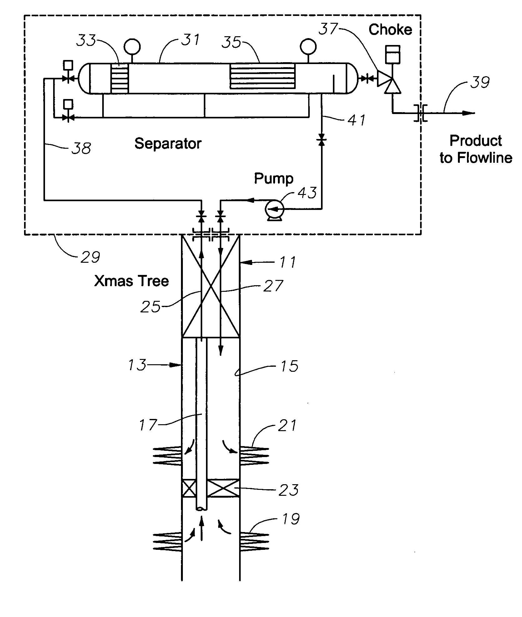
Figure 1 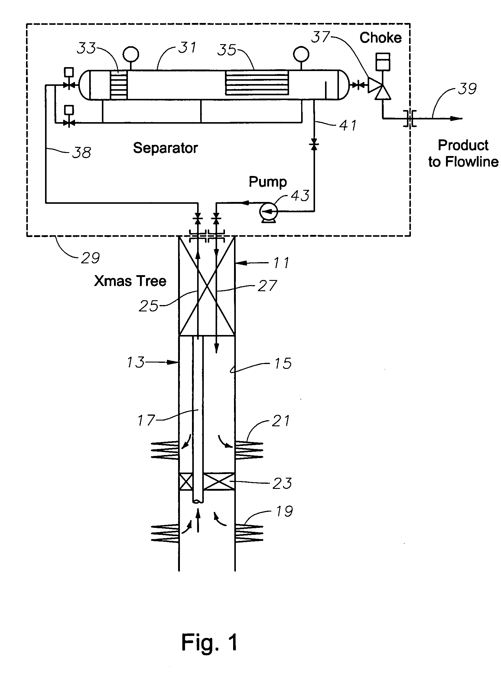
Figure 2 
Figure 3
Abstract
Description
FIELD OF THE INVENTION
[0001] This invention relates in general to subsea well oil and gas production, and in particular to a system having a subsea separator and injection pump for injecting separated waste fluid back into the well. BACKGROUND OF THE INVENTION
[0002] One type of subsea well production utilizes a subsea Christmas tree located at the sea floor at the upper end of the well. The Christmas tree has valves and a choke for controlling the well fluid being produced.
[0003] In one type of production, the fluid flows from the tree to a production platform at the surface. The production platform has separators for separating waste products, such as water, from the well fluid. One method to dispose of the separated water is to pump it back down conduits to subsea injection wells. This system requires sufficiently high pressure in the well in order to convey the well fluid, which still contains water, to the production platform. In very deep water, the well pressure may be inad...