Vibratory Separator

a separator and vibrating technology, applied in the field of vibrating separators, can solve the problems of time-consuming and expensive mud evaluation and mixture process, affecting the quality of filtration separation,

Active Publication Date: 2007-06-14
MI
View PDF8 Cites 64 Cited by
  • Summary
  • Abstract
  • Description
  • Claims
  • Application Information

AI Technical Summary

Problems solved by technology

Because the mud evaluation and mixture process is time consuming and expensive, drillers and service companies prefer to reclaim the returned drilling mud and recycle it for continued use.
The flow rate may increase to such an extent that the mesh of the screening surface can become congested with solids that are not removed fast enough to allow the fluid component of the feed mud to flow through the screen.
This often results in the presence of a small gap between the back edge of the basket and the housing.
As drilling fluid solids are filtered from the drilling fluid, the wires making up the screening surface are subject to breakage.
As the wires break, a hole or tear in the screen forms and becomes larger, whi...

Method used


Image

  • Vibratory Separator
  • Vibratory Separator
  • Vibratory Separator

Examples


Embodiment Construction

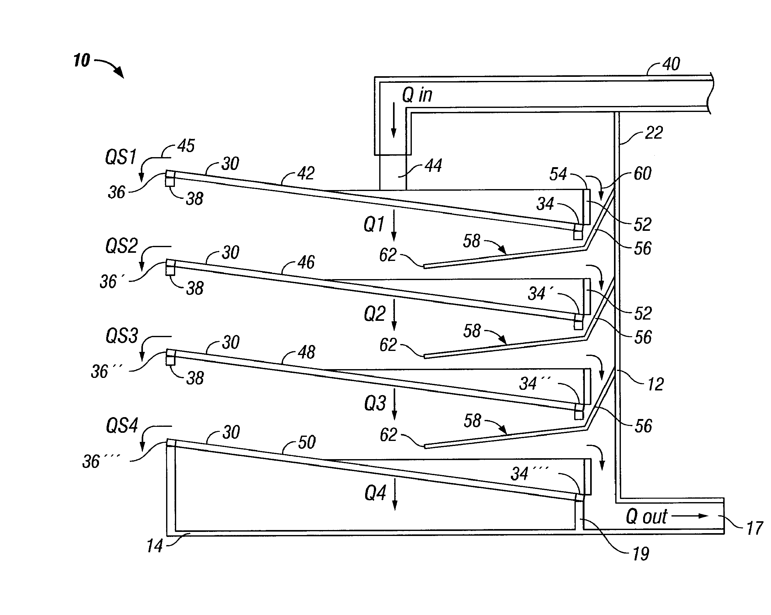
[0020] In one aspect, embodiments disclosed herein relate to a shale shaker having a screen arrangement precluding the loss of whole mud over the front edge of the screening surface. Specifically the embodiments disclosed herein relate to a shale shaker having an arrangement of screening surfaces, weirs, and a flow director to direct excess fluid to a subsequent screening surface or a collection area for recirculation through the shaker.

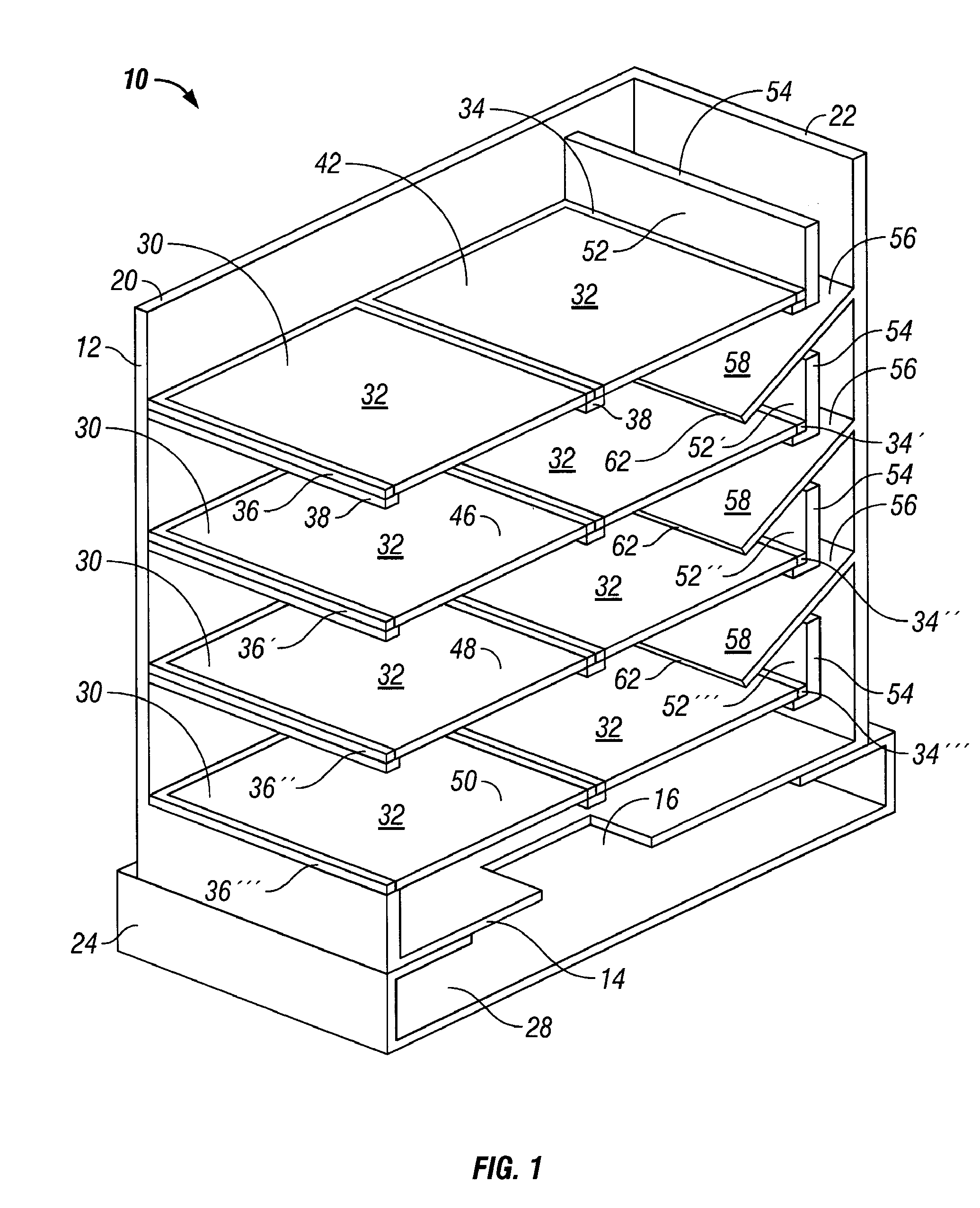
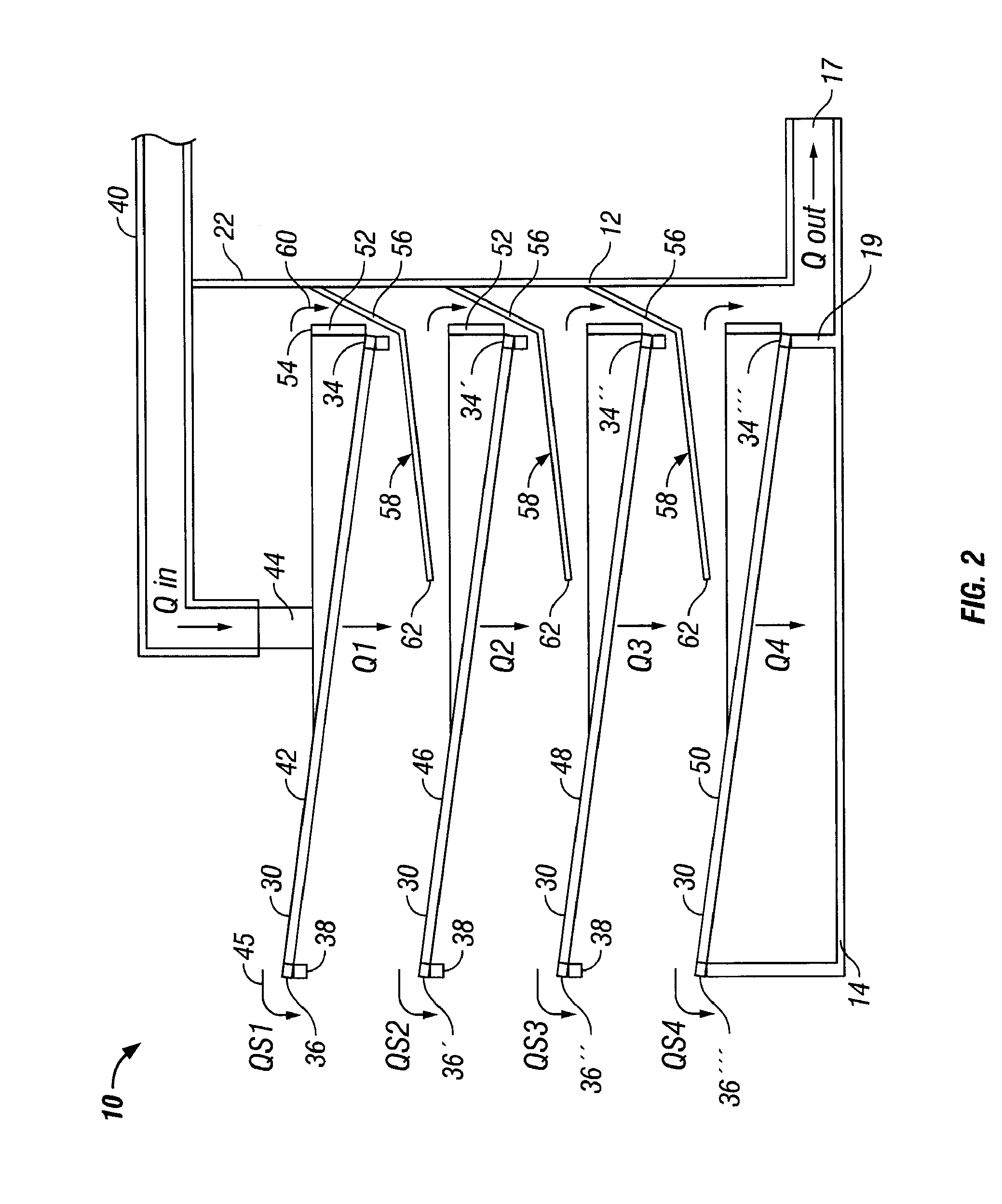
[0021] Referring to FIGS. 1 and 3, a shaker in accordance with an embodiment of the present invention is shown. The reference numeral 10, refers, in general, to a vibrating screen separator assembly that includes a basket 12 that includes a bottom wall 14 having an opening 16, a pair of side walls, 18 and 20 (side wall 18 shown in FIG. 3), and an end wall 22. Side walls 18 and 20 are spaced-apart and have first ends and second ends. The first ends of each side wall 18, 20 are connected to end wall 22, wherein the end wall is located at the feed end ...


PUM

PropertyMeasurementUnit
Flow rateaaaaaaaaaa
Heightaaaaaaaaaa
Mesh sizeaaaaaaaaaa

Abstract

An apparatus for separating solids from a drilling fluid that includes a basket having two opposed spaced-apart side walls having first ends and second ends, the first ends spaced apart by an end wall connected to each of the side walls, the basket further including a bottom wall through which a fluid outlet passage is defined, a plurality of screening surfaces having a front edge and a back edge and positioned within the basket between the side walls with each screening surface spaced apart vertically from adjacent screening surfaces and the back edge spaced apart from the end wall of the basket, wherein the back edge of each screening surface is lower than the front edge of the corresponding screening surface, a plurality of weirs, each weir retained along the back edge of a corresponding screening surface and spaced apart from the end wall to define a fluid passage between each weir and the end wall, wherein each weir has a top edge extending to a weir height above the back edge of the corresponding screening surface and the top edge is lower than the front edge of the corresponding screening surface, at least one flow director catching unseparated drilling fluid in the fluid passage and directing the unseparated drilling fluid onto a lower screen, and wherein fluid in the fluid passage between the lowermost screen and the end wall is directed to a spillover fluid outlet is disclosed.

Description

[0001] This application claims the benefit of U.S. Provisional Application No. 60 / 750,090, filed Dec. 13, 2005 and U.S. Provisional Application No. 60 / 827,453, filed Sep. 29, 2006 the contents of which are incorporated herein by reference.BACKGROUND OF INVENTION [0002] Oilfield drilling fluid, often called “mud,” serves multiple purposes in the industry. Among its any functions, the drilling mud acts as a lubricant to cool rotary drill bits and facilitate faster cutting rates. The mud is mixed at the surface and pumped downhole through a bore of the drillstring to the drill bit where it exits through various nozzles and ports, lubricating and cooling the drill bit. After exiting through the nozzles, the “spent” fluid returns to the surface through an annulus formed between the drillstring and the drilled wellbore. [0003] Furthermore, drilling mud provides a column of hydrostatic pressure, or head, to prevent “blow out” of the well being drilled. This hydrostatic pressure offsets for...

Claims


Application Information

Patent Timeline
IPC IPC(8): B07B1/49
CPCB01D21/283B01D33/0376B01D2201/48B07B1/46B07B2201/04B07B2230/01E21B21/065B01D33/00
Inventor BROWNE, NEALECARR, BRIAN
Owner MI
Why Eureka
Try Eureka