Method for correcting image artifacts due to detector overexposure in computed tomography

a computed tomography and image artifact technology, applied in the direction of material analysis using wave/particle radiation, instruments, nuclear engineering, etc., can solve the problem of disturbing capping artifacts in reconstructed images, and achieve simple and efficient correction, improve low contrast resolution in images, and reduce capping artifacts

Inactive Publication Date: 2007-06-14
SIEMENS HEALTHCARE GMBH
View PDF1 Cites 1 Cited by
  • Summary
  • Abstract
  • Description
  • Claims
  • Application Information

AI Technical Summary

Benefits of technology

[0006] It is an object of the present invention to provide a simple and efficient correction method that is able to decrease capping artifacts in computed tomography images, that arise due to detector overexposure, thereby resulting in better low contrast resolution in the image and a substantial improvement in the quality of the reconstructed image.

Problems solved by technology

Capping artifacts occur because, even for a homogenous object, the reconstructed Hounsfield values are not reduced by a simple DC offset, but become increasingly smaller toward the edges of the object.
Capping artifacts are very disturbing for detecting low contrast objects in the reconstructed images.

Method used


Image

  • Method for correcting image artifacts due to detector overexposure in computed tomography
  • Method for correcting image artifacts due to detector overexposure in computed tomography
  • Method for correcting image artifacts due to detector overexposure in computed tomography

Examples


Embodiment Construction

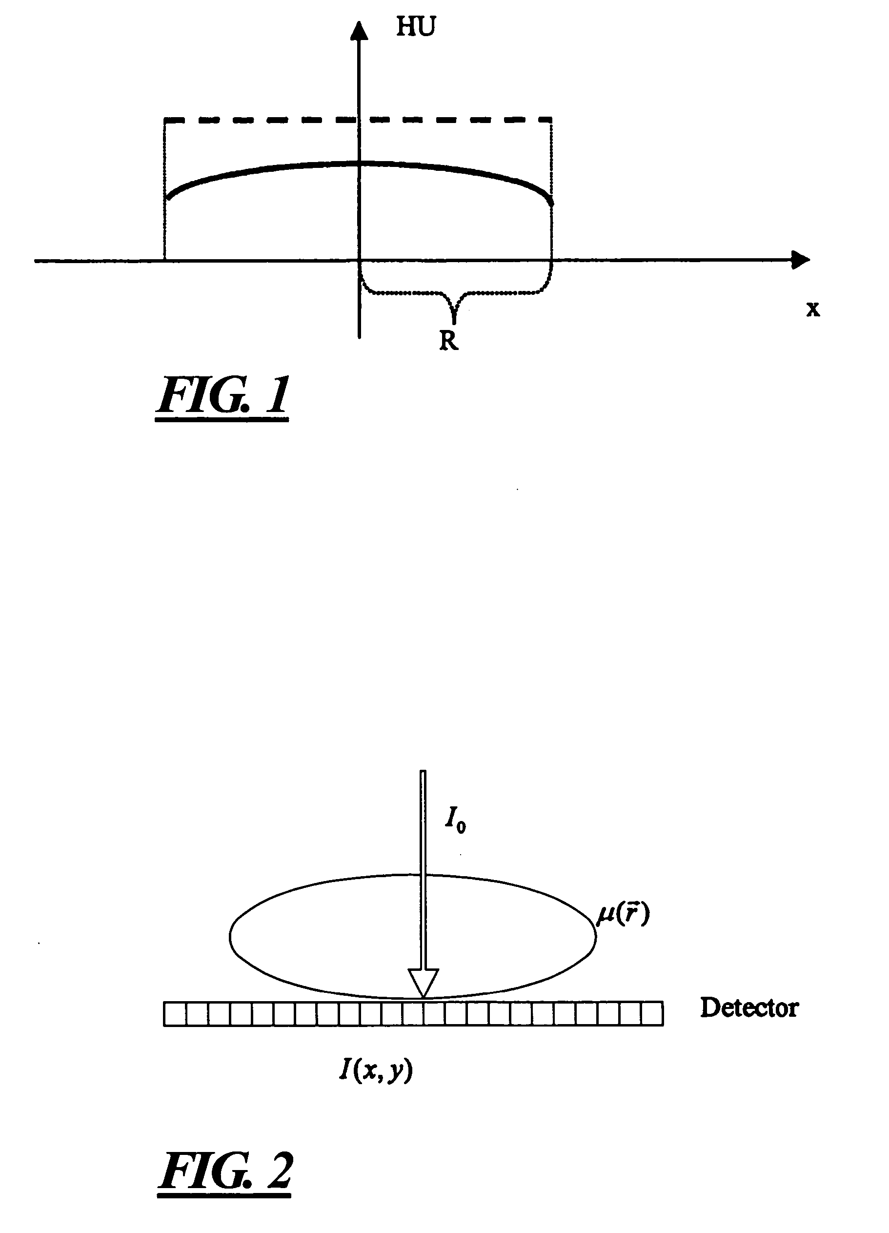
[0016] The phenomenon of clipping, as discussed above is schematically illustrated in FIG. 1, which shows Hounsfield values for a homogenous cylinder with a radius R along the direction of the x-axis, with Hounsfield values HU along the vertical axis. Due to the above-discussed overexposure, the resulting Hounsfield values of the image reconstruction are smaller at the edges, thereby causing a line under consideration (solid curved line) to exhibit a capping artifact, compared to the dashed line of the image, wherein no capping artifact exists.

[0017] The following provides general background information for use in explaining the inventive method and its application in the field of angiographic computed tomography imaging.

[0018] The input for the image reconstruction algorithms must be line integrals ∫μ( r)ds of the object of interest. Line integrals are defined as follows: ∫μ⁡(r_)⁢ ⁢ⅆs=ln⁡(l0l⁡(x,y))

wherein I0 is the maximum intensity when no object is present I(x,y) is the meas...


PUM


Abstract

In a method for reconstructing a 3D CT image from a number of 2D projection images each 2D projection image is divided at an arbitrarily selectable position by a substantially vertical image line and the projection image is automatically electronically analyzed to detect whether clipping occurs on the left side or on the right side, or on both sides, of the image line. For each side of the image line at which clipping is detected, a horizontal coordinate at which the clipping ends is identified. The grayscale values at the side of the horizontal coordinate opposite to the side at which the image line is located are extrapolated so that the clipping is removed. The corrected 2D projection images are then used to reconstruct a 3D image, in which capping artifacts, that would otherwise be present, or avoided or substantially minimized due to the corrections made in the 2D projections.

Description

BACKGROUND OF THE INVENTION [0001] 1. Field of the Invention [0002] The present invention is directed to a method used in the reconstruction of an image from computed tomography data to correct artifacts in the image arising due to overexposure of the radiation detector of the computed tomography apparatus. [0003] 2. Description of the Prior Art [0004] The use of flat panel digital detectors for detecting x-ray radiation in computed tomography is becoming increasingly common. Typical flat panel digital detectors that are suitable for this type of use have a dynamic range of 14 bits. Digital image pixel processors that are conventionally used to process the raw image data reduce the dynamic range to only 12 bits, which is relatively small compared to the dynamic range of conventional computed tomography radiation detector, which typically is between 18 and 20 bits. [0005] A dynamic range of 12 bits often is not large enough to avoid overexposure in the 2D projection images, namely th...

Claims


Application Information

Patent Timeline
Patent Type & Authority Applications(United States)
IPC IPC(8): H05G1/64
CPCG06T11/005
Inventor SCHREIBER, BERNDBRUNNER, THOMAS
Owner SIEMENS HEALTHCARE GMBH
Why Eureka
Try Eureka