Speaker and method of outputting acoustic sound

a technology of acoustic sound and a speaker, which is applied in the direction of diaphragm construction, transducer types, electrical transducers, etc., can solve the problems of difficult to obtain a global acoustic image, and achieve the effect of ensuring independency on vibration, less distortion in sound image, and enhancing global acoustic imag

Active Publication Date: 2007-06-14
SONY CORP
View PDF2 Cites 39 Cited by
  • Summary
  • Abstract
  • Description
  • Claims
  • Application Information

AI Technical Summary

Benefits of technology

[0020] For example, a plurality of the actuators can be provided. The transmission portions of the actuators are respectively attached to different positions of the acoustic diaphragm. For example, driving the plurality of the actuators based on, for example, the same acoustic signal allows omni-directionality to be obtained. Further, driving the plurality of the actuators respectively by the separate acoustic signals, for example, the acoustic signals of plural channels, plural acoustic signals obtained by adjusting the identical acoustic signal independently on its level, its delay time, or its frequency characteristic, or the like allows to be implemented any sound field processing to enhance the global acoustic image.
[0021] For example, the acoustic diaphragm can be made of a plurality of split acoustic diaphragms that are completely or partially away from each other. In this speaker, the transmission portions of the plurality of the actuators are respectively attached to the corresponding split acoustic diaphragms, thereby securing independency on vibration of each of the actuators. This allows, for example, the above sound field processing to be effectively performed.
[0022] For example, the acoustic diaphragm may be set with its one end being put at the lower side, and the actuator may be mounted on the other end of the acoustic diaphragm with the transmission portion of the actuator being attached to the other end of the acoustic diaphragm. This enables the actuator without any fixation to propagate its vibration to the acoustic diaphragm by inertial force, thereby causing a less distortion in the sound image because the actuator is not restrained.
[0023] Since, according to the embodiment of the invention, the transmission portion of the actuator which transmits a displacement output thereof to the acoustic diaphragm is attached to the acoustic diaphragm and the actuator vibrates with the acoustic diaphragm by at least its component of the vibration along the plane of the acoustic diaphragm, it is possible to obtain a global acoustic image.

Problems solved by technology

Thus, in the acoustic output device 300, it is difficult to obtain a global acoustic image.

Method used


Image

  • Speaker and method of outputting acoustic sound
  • Speaker and method of outputting acoustic sound
  • Speaker and method of outputting acoustic sound

Examples


Embodiment Construction

[0064] The following will describe embodiments of the present invention with reference to the accompanied drawings.

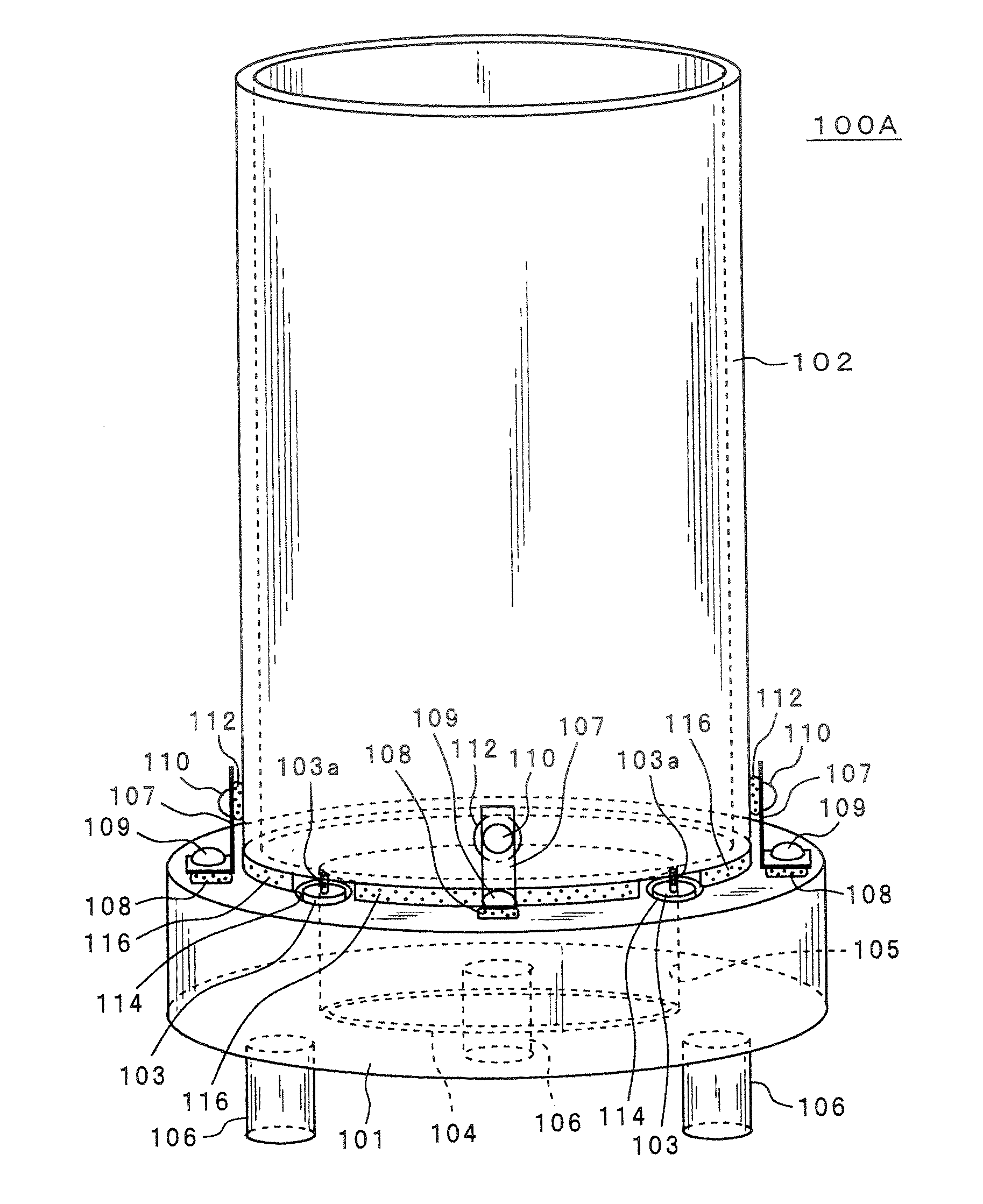
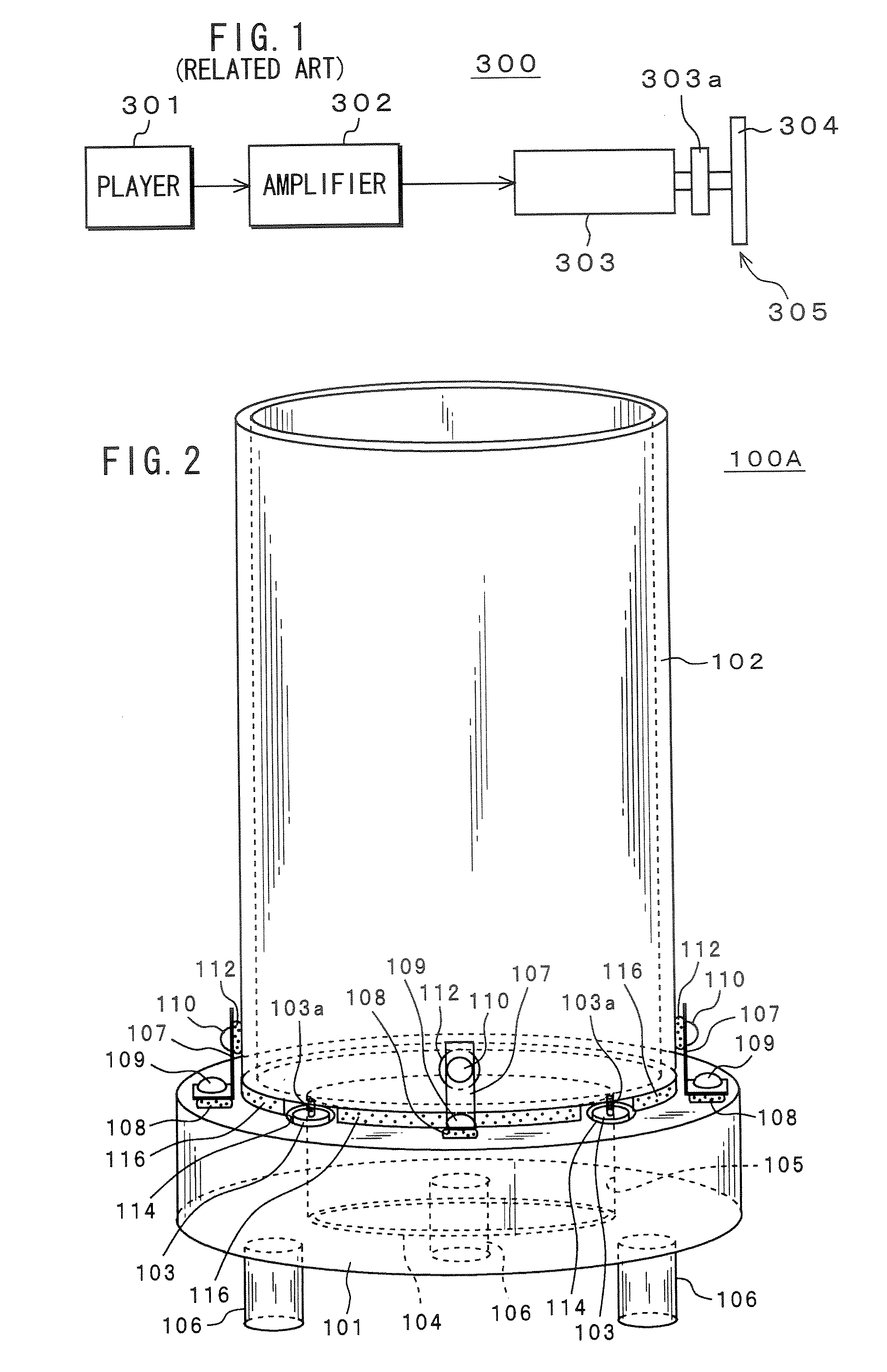
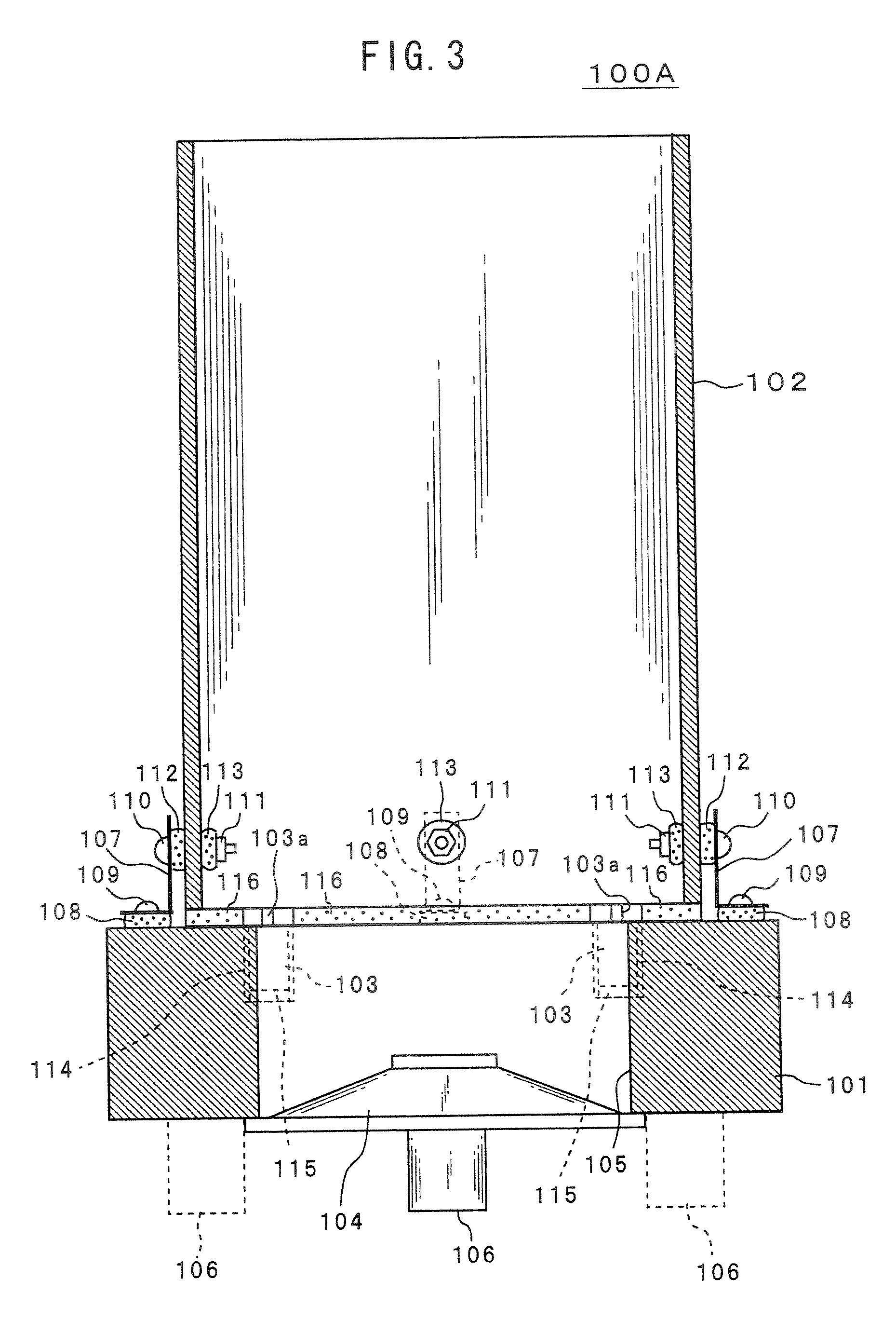
[0065]FIGS. 2 through 5 show a configuration of an embodiment of a speaker according to the invention. FIG. 2 is a perspective view of a speaker 100A according to an embodiment of the invention; FIG. 3 is a vertical sectional view thereof; FIG. 4 is a top plan view thereof; and FIG. 5 is a bottom plan view thereof.

[0066] The speaker 100A has a base casing 101, a pipe member 102, a magnetostrictive actuator 103 as an actuator, and a speaker unit 104. The pipe member 102 constitutes a diaphragm of tube as an acoustic diaphragm. A driving rod 103a of the magnetostrictive actuator 103 constitutes a transmission portion which transmits a displacement output of the magnetostrictive actuator 103.

[0067] The base casing 101 is made of, for example, synthetic resin. This base casing 101 has a shape like a disk as a whole and a cylindrical opening 105 passing through it at a ce...


PUM


Abstract

A speaker has an acoustic diaphragm, and an actuator that is driven based on an acoustic signal. The actuator has a transmission portion that is directly or indirectly attached to the acoustic diaphragm and transmits a displacement output of the actuator to the acoustic diaphragm. The actuator vibrates with the acoustic diaphragm by at least its component of the vibration along a plane of the acoustic diagram.

Description

CROSSREFERENCE TO RELATED APPLICATION [0001] The present invention contains subject matters related to Japanese Patent Application JP 2005-356751 filed in the Japanese Patent Office on Dec. 9, 2005, the entire contents of which being incorporated herein by reference. BACKGROUND OF THE INVENTION [0002] 1. Field of the Invention [0003] The present invention relates to a speaker and a method of outputting acoustic sound. More particularly, it relates to a speaker and the like in which an actuator driven based on an acoustic signal is used to vibrate with a diaphragm, thereby obtaining an acoustic output. [0004] 2. Description of Related Art [0005] Japanese Patent Application Publication No. H04-313999 has disclosed a speaker, in which a magnetostrictive actuator is used to vibrate with a diaphragm, thereby obtaining an acoustic output sound. The magnetostrictive actuator is referred to as an actuator in which a magnetostrictive element whose form can alter by applying an external magne...

Claims


Application Information

Patent Timeline
Patent Type & Authority Applications(United States)
IPC IPC(8): H04R9/06
CPCH04R1/26H04R1/288H04R1/323H04R3/14H04R7/04H04R7/12H04R15/00H04R9/00
Inventor SUZUKI, NOBUKAZUURYU, MASARUOHASHI, YOSHIO
Owner SONY CORP
Why Eureka
Try Eureka