
Security mesh panel

a mesh panel and security technology, applied in the field of security panels, can solve the problems of inconvenient use, high cost of materials for many applications, and weak joints in each join, so as to improve the overall strength of the security panel and improve the security of the panel. , the effect of strong durability

Inactive Publication Date: 2007-06-21
THE EXPANDED METAL GROUP PTE
View PDF10 Cites 12 Cited by
  • Summary
  • Abstract
  • Description
  • Claims
  • Application Information

AI Technical Summary

Benefits of technology

[0009] Because the security panel is formed from an expanded mesh, there is no need for welds or rivets at mesh nodes. The panel therefore has an inherent strength and durability beyond that which may be achieved with a security panel formed from individual lengths of razor wire. Furthermore, there is no need for there to be any welds or other joins between the barbed structures and the mesh at the mesh nodes. Such joins can be made entirely away from the mesh nodes. Therefore, the formation and performance of these joins cannot adversely affect the strength of the mesh at the nodes. Because any stresses on a security panel will tend to be concentrated at one or more of the mesh nodes, the overall strength of the security panel can readily be improved as compared with a security panel having joins between individual pieces of razor wire.
[0010] Preferably, the barbed structures are affixed to all sides of said at least one aperture. This helps to provide the maximum number of the barbs projecting into each aperture of the security panel, thereby improving the security of the panel. Furthermore, for the same reason the barbed structure may have a plurality of said barbs extending in the plane of the panel in towards another side of said aperture.

Problems solved by technology

A number of problems have been noted with such security mesh panels.
First, a large number of individual strands of razor wire have to be formed and aligned relative to one another prior to fixing the strands together.
Second, although in principle it is possible to make a weld or rivet as strong as the surrounding material, in practice each join is a potential source of weakness.
Both welds and rivets are a potential source of corrosion, either from the use of differing types of metals in the same structure, or from damage done to a galvanized protective finish on the original razor wire.
One solution to the latter problem is to form the razor wire from stainless steel, but this is a prohibitively expensive material to use in many applications, particularly perimeter fencing formed from the security mesh panels.

Method used


Image

  • Security mesh panel
  • Security mesh panel
  • Security mesh panel

Examples


Embodiment Construction

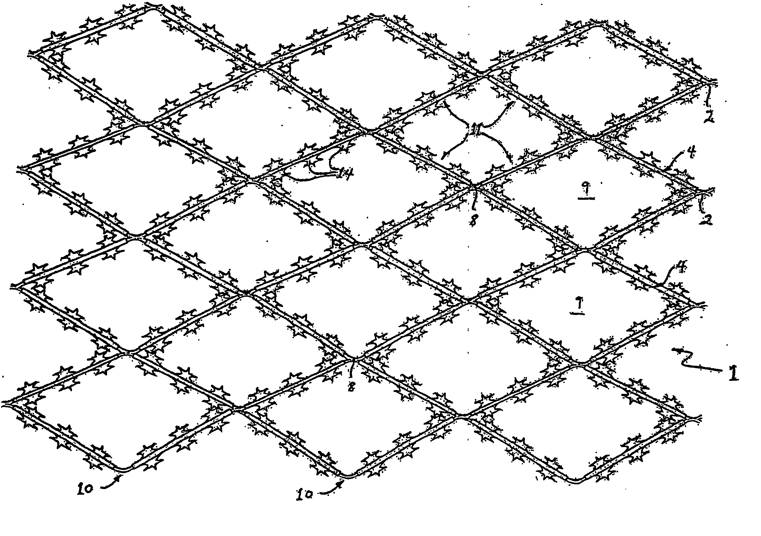
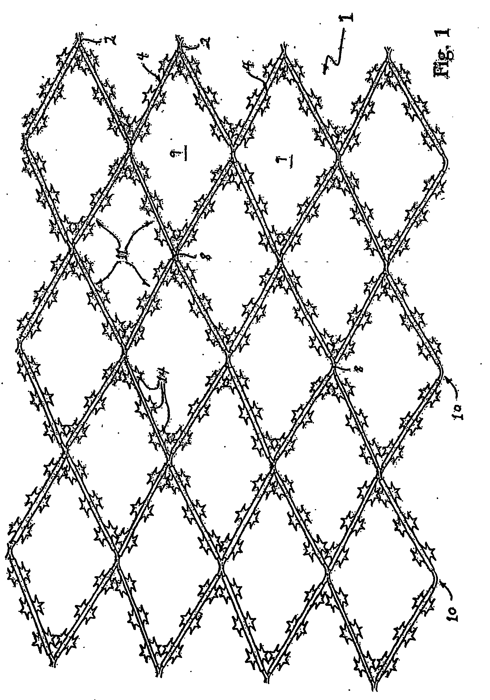
[0023]FIG. 1 shows a plan view of one side of a security mesh panel 1. The security panel 1 is formed from a planar expanded metal mesh 2 to which individual elongate metal barbed structures 4 have been permanently affixed, for example by spot welding. The expanded mesh 2 is itself formed in a conventional manner from a metal sheet, for example 3 mm thick mild steel, galvanized steel or even stainless steel, through which a series of parallel non-overlapping slits have been punched. After the slits have been formed, a pair of opposite edges of the sheet is pulled apart to expand the sheet and form the mesh 2. If the expanded metal sheet requires corrosion protection, then it may be galvanized.

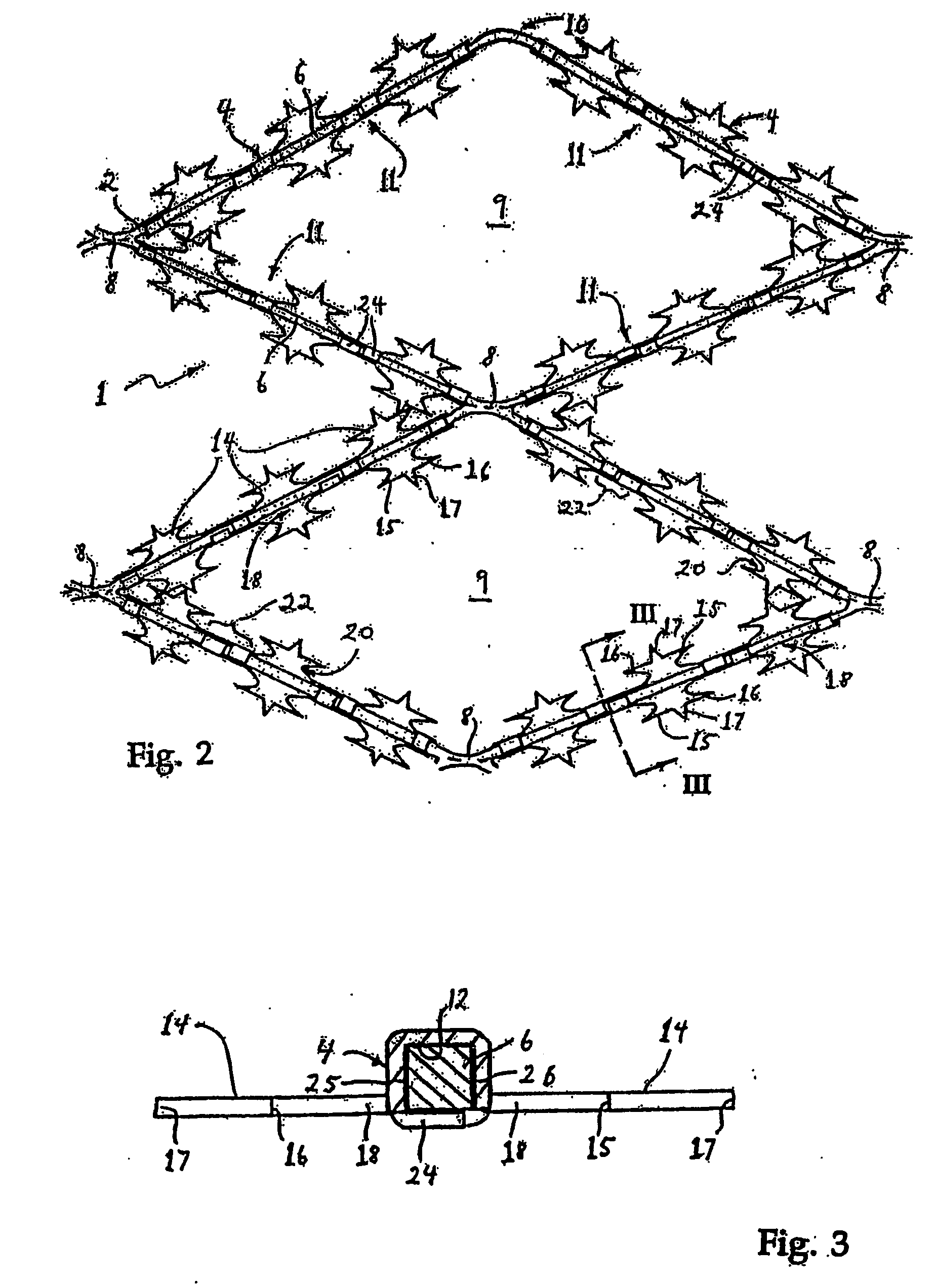
[0024] Reference is now made also to FIGS. 2 and 3, which show respectively an enlarged plan view of a side of the security mesh 2 opposite to that shown in FIG. 1, and a cross section view through the security mesh. The mesh 2 consists of a series of adjacent strips of metal 6, which in this ...


PUM


Abstract

The present invention relates to a security panel (1), for example for use in a security barrier, and to a method of forming the security panel. The security panel (1), comprises an expanded metal mesh (2), the mesh hating apertures (9) therethrough bounded by a plurality of sides (11), at least one of said apertures (9) having at least one side (11) to which is affixed a separate barbed structure (4), the barbed structure having at least one barb (14) extending in a plane of the panel (1) in towards another side (11) of said aperture (9).

Description

FIELD OF THE INVENTION [0001] The present invention relates to a security panel, for example for use in a security barrier, and to a method of forming the security panel. BACKGROUND [0002] Security barriers are conventionally formed from straight sections of elongated metal tape having barbs formed at spaced intervals along the tape. The metal tape may be traditional barbed wire, which usually comprises two or more braided wires with regularly spaced intertwined wire barbs. Alternatively, the metal tape may be razor wire, which usually has a central wire with laterally extending planar barbs. An example of such razor wire is disclosed in U.S. Pat. No. 4,509,726. [0003] It is known to form metal tape, and particularly razor wire, into a security mesh panel in order to provide a barrier which is both stronger and more secure than a barrier formed purely with elongate parallel strands of metal tape. One such security mesh is disclosed in patent document CA 1,190,433, which shows a secu...

Claims


Application Information

Patent Timeline
IPC IPC(8): B21F25/00E04H17/04
CPCE04H17/04B21F25/00
Inventor YEO, JEFFREY S.K.
Owner THE EXPANDED METAL GROUP PTE
Learn More