Ink-jet recording apparatus including pump, method for controlling the ink-jet recording apparatus, and method for controlling the pump

a technology of inkjet recording apparatus and pump, which is applied in the direction of printing, etc., can solve the problems of ink not being smoothly supplied to the ink-jet head, failure of the pump, etc., and achieve the effect of preventing the breakage of the meniscus and substantially maintaining the pressure within the cavity

Inactive Publication Date: 2007-06-21
BROTHER KOGYO KK
View PDF3 Cites 0 Cited by
  • Summary
  • Abstract
  • Description
  • Claims
  • Application Information

AI Technical Summary

Benefits of technology

[0010] An object of the present invention is to provide an ink-jet recording apparatus comprising a pump that is unlikely to cause a failure, a method for controlling the ink-jet recording apparatus capable of preventing a failure of the pump, and a method for controlling the pump capable of preventing a failure.
[0022] The apparatuses or methods according to the aforementioned first to tenth aspects do not adopt such a system that, as in the prior art, a tube disposed within a pump is subjected to repeated pressurization and depressurization. Therefore, the pump has a relatively simple construction, and at the same time the pump is unlikely to incur a failure that would otherwise be caused by, e.g., damage on a tube. Thus, the ink-jet head can be prevented from seeing a defective ink supply that would be caused by a failure of the pump.
[0024] Further, in the apparatus or methods according to the aforementioned eighth to tenth aspects, based on a result of detection by the detector, the partition is disposed within the above-described ranges prior to dismounting from the pump the ink supply member that supplies ink to the pump, and then the ink supply member is dismounted from the pump with the partition being kept within the above-described ranges. As a result, pressure within the cavity can substantially be kept constant during a dismounting of the ink supply member. This can prevent breakage of meniscuses.

Problems solved by technology

This causes damage on the tube, which means a failure of the pump, and therefore raises a problem that ink cannot smoothly be supplied to the ink-jet head.

Method used


Image

  • Ink-jet recording apparatus including pump, method for controlling the ink-jet recording apparatus, and method for controlling the pump
  • Ink-jet recording apparatus including pump, method for controlling the ink-jet recording apparatus, and method for controlling the pump
  • Ink-jet recording apparatus including pump, method for controlling the ink-jet recording apparatus, and method for controlling the pump

Examples


Embodiment Construction

[0039] In the following, some preferred embodiments of the present invention will be described in conjunction with the accompanying drawings.

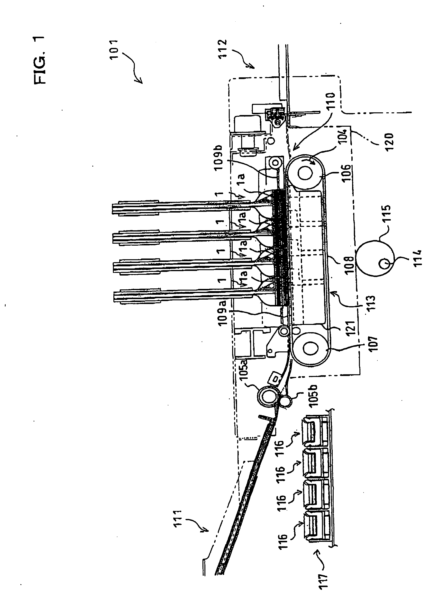
[0040] First, referring to FIG. 1, a description will be given to a general construction of an ink-jet printer according to an embodiment of the present invention. An ink-jet printer 101 of this embodiment is a color printer having four ink-jet heads 1. The printer 101 includes a paper feed unit 111 (as shown lefthand in FIG. 1) and a paper discharge unit 112 (as shown righthand in FIG. 1). Within the printer 1, formed is a paper conveyance path running from the paper feed unit 111 to the paper discharge unit 112.

[0041] A pair of paper feed rollers 105a and 105b are disposed immediately downstream from the paper feed unit 111, so that the rollers 105a and 105b can pinch a paper as a record medium which is in this condition conveyed from left to right in FIG. 1. In a middle of the paper conveyance path and below the four heads 1, a conveyance ...


PUM


Abstract

An ink-jet recording apparatus comprises a pump, an ink-jet head, and a detector. The pump includes a housing, a rotor, a partition, a first passage, and a second passage. The housing has a cavity formed therein and also has an inlet port through which ink is sucked into the cavity and an outlet port through which ink is discharged out of the cavity. The rotor is rotatable within the cavity. The partition is, together with the rotor, rotatable within the cavity while being supported on the rotor such that both ends thereof can be in contact with an inner surface of the housing. The first passage is formed within the cavity and extends from the inlet port to the outlet port. The second passage is formed within the cavity to be longer than the first passage and extends from the inlet port to the outlet port via a side of the rotor opposite to the first passage. To the ink-jet head, ink is supplied from the pump. The detector detects whether or not the partition is disposed within such a range that a flow resistance in the first passage can be higher than a flow resistance in the second passage.

Description

[0001] This is a Division of application Ser. No. 10 / 948,195 filed Sep. 24, 2004. The disclosure of the prior application is hereby incorporated by reference herein in its entirety.BACKGROUND OF THE INVENTION [0002] 1. Field of the Invention [0003] The present invention relates to an ink-jet recording apparatus comprising a pump that sucks liquid therein and discharges the liquid thereout, to a method for controlling the ink-jet recording apparatus, and to a method for controlling the pump. [0004] 2. Description of Related Art [0005] An ink-jet recording apparatus such as ink-jet printers comprises an ink-jet head formed with a large number of nozzles through which ink is ejected. The ink-jet head is connected, through a tube or the like, with an ink cartridge that serves as an ink supply source. During a printing operation, the ink-jet head sucks ink from the ink cartridge by making use of a capillary effect within the nozzles and a difference between the ink cartridge and the nozz...

Claims


Application Information

Patent Timeline
Patent Type & Authority Applications(United States)
IPC IPC(8): B41J2/175
CPCB41J2/17596
Inventor TAKAGI, OSAMU
Owner BROTHER KOGYO KK
Why Eureka
Try Eureka