
Real-time wireless sensor network protocol having linear configuration

a real-time wireless sensor and network protocol technology, applied in the field of sensor networks, can solve the problems of control packet overhead, waste of energy in a wireless network, and the minimum energy used to transmit sensing data, and achieve the effect of high link connection quality

Active Publication Date: 2007-06-21
KOREA ELECTRONICS TECH INST
View PDF5 Cites 49 Cited by
  • Summary
  • Abstract
  • Description
  • Claims
  • Application Information

AI Technical Summary

Benefits of technology

[0025] Example embodiments of the present invention also provide a protocol for a low power sensor network by minimizing an idle listening time of an active interval at a periodical operation of a sleep / active state.
[0029] In still other example embodiments, a new node joining method of a sensor network configured to collect detecting data from a plurality of sensors and of which respective node has a communication path of a serially linear structure includes: communicating a hello message configured to enable a terminal node located in the endmost position of the linear sensor network to periodically notify its own presence; enabling one or more sensor nodes configured to be newly joined to the sensor network to compute a link connection quality from a signal state of the hello message received to its own; enabling the sensor node having the highest link connection quality to communicate a preemptive message; enabling the sensor node to transmit a join message to the present terminal node in a next interval after communicating the preemptive message; and enabling the sensor node to advertise that the node becomes a new terminal node in case of receiving an ACK message corresponding to the join message.

Problems solved by technology

Since respective nodes in the sensor network, especially in wireless networks, use a limited capacity of battery, a main problem of the sensor network is to transmit sensing data using the minimum energy.
Problems such as pack collision, overhearing, control packet overhead, idle listening and the like, which energy is wasted in a wireless network, are arisen in case that a conventional MAC protocol such as an existing MANET and IEEE802.11 is applied to the sensor network.
Specifically, the idle listening consumes most of energy, according as a sensor node is always operated in active state even in an interval of which a communication function is not required.
The S-MAC protocol converts periodically a sensor node into a sleeping mode with a low duty cycle so as to reduce idle listening, a main cause of the energy consumption in the wireless network.
However, it has a disadvantage of increasing network latency due to the idle listening.
However, according as the duty cycle proposed in the S-MAC is applied in a fixed form, the efficiency of energy saving is reduced due to a change of traffic environment.
However, similarly to the S-MAC, a problem of increasing network latency is still remained due to the idle listening.
The B-MAC also generates a lot of energy consumption.
However, the energy efficiency of the S-MAC is greatly decreased in case of the node senses a very small volume of data in the sensor network, because of an unnecessary idle listening.
And since the above duty cycle can not be adopted in an environment that a volume of network traffic is very high, it is difficult to effectively obtain an effect of energy saving.
The S-MAC or the T-MAC and B-MAC additionally consumes energy for transmitting or receiving a control packet or a long preamble except that energy is basically consumed to transmit data, and also consumes energy through idle listening for a specific interval depending on the traffic environment.
Additionally, the S-MAC and the T-MAC generate additional energy consumption by using a CSMA-CA type, and the B-MAC additionally generates energy consumption due to overhearing.
An existing MAC protocol for sensor network has a very big disadvantage in network latency.
This arises a severe problem in case that a real-time application is needed while using the limited power supply such as the battery.
Specifically, the network latency is seriously affected in case that the sensor networks are in large scale.
However, the above-described conventional communication type does not show a method for giving a priority in transmission.
Specifically, in case that the technology of the sensor network is applied to emergency situation monitoring, the reliability becomes the most important issue.
The existing conventional sensor network protocol just has considered reliability as a transmission issue.
However, in order to assure the reliability, it is also needed to monitor the sensor nodes are in an error or are not operated.

Method used


Image

  • Real-time wireless sensor network protocol having linear configuration
  • Real-time wireless sensor network protocol having linear configuration
  • Real-time wireless sensor network protocol having linear configuration

Examples


Embodiment Construction

[0040] Example embodiments of the present invention are disclosed herein. However, specific structural and functional details disclosed herein are merely representative for purposes of describing example embodiments of the present invention, however, example embodiments of the present invention may be embodied in many alternate forms and should not be construed as limited to example embodiments of the present invention set forth herein.

[0041] Accordingly, while the invention is susceptible to various modifications and alternative forms, specific embodiments thereof are shown by way of example in the drawings and will herein be described in detail. It should be understood, however, that there is no intent to limit the invention to the particular forms disclosed, but on the contrary, the invention is to cover all modifications, equivalents, and alternatives falling within the spirit and scope of the invention. Like numbers refer to like elements throughout the description of the figu...


PUM


Abstract

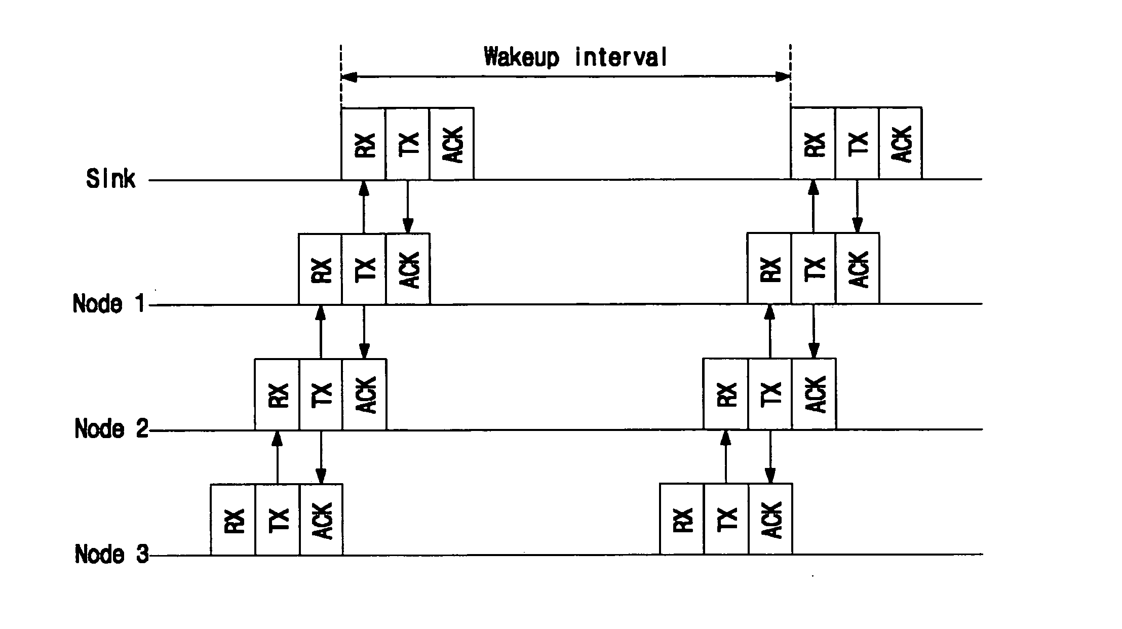
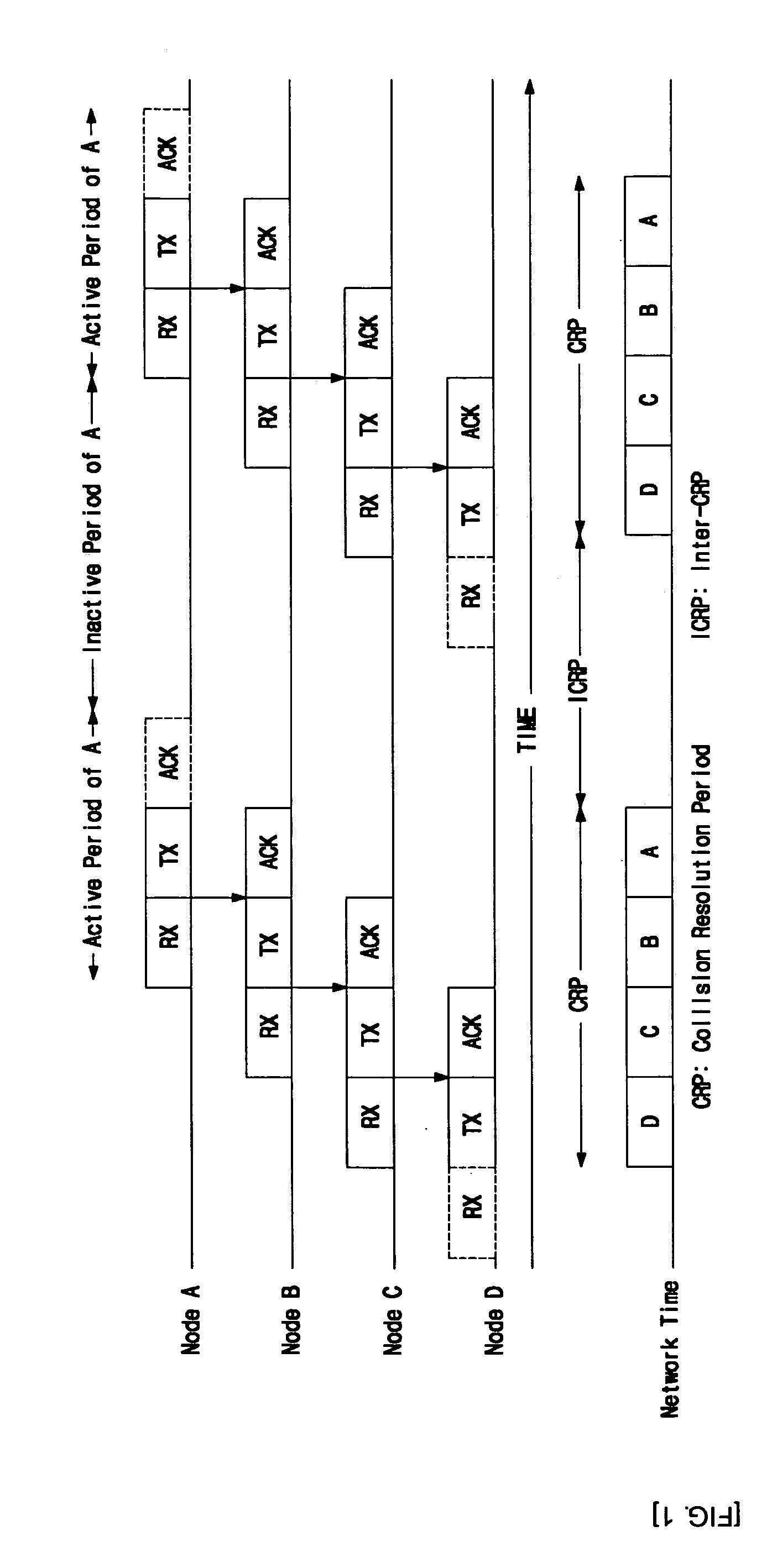
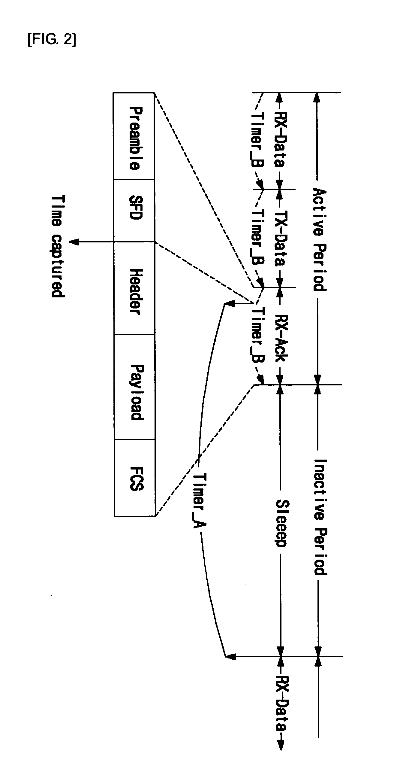
A network configuration method of a sensor network configured to collect sensed data from a plurality of sensor nodes comprising: arranging linearly a path of respective node so as to enable all sensor nodes except for a sink node and a terminal node to have respectively a predecessor and a successor; and setting the time synchronization of whole network by fixing the each node take its own time synchronization on the basis of an operation section of the predecessor.

Description

CLAIM FOR PRIORITY [0001] This application claims priority to Korean Patent Application No. 10-2005-0126887 filed on 21 Dec. 2005, in the Korean Intellectual Property Office (KIPO), the entire contents of which are hereby incorporated by reference. BACKGROUND [0002] 1. Field of the Invention [0003] The present invention relates in general to the field of a sensor network, and more specifically to a communication protocol between sensor nodes. [0004] 2. Description of the Related Art [0005] A sensor network is a core technical infra configured to realize ubiquitous computing technology and may be operated by wire or wireless connection. Since respective nodes in the sensor network, especially in wireless networks, use a limited capacity of battery, a main problem of the sensor network is to transmit sensing data using the minimum energy. Further, network latency must be reduced to the minimum in a large sensor network for the purpose of applying the sensor network to a real-time emer...

Claims


Application Information

Patent Timeline
IPC IPC(8): H04J3/06
CPCB61L27/0088H04W56/00H04J3/0652H04J3/0655Y02B60/50Y02D30/70B61L27/53H04W84/18
Inventor KIM, JAE-HOLEE, SANG-SHINAHN, IL-YEUPWON, KWANG-HOKIM, SEONG-DONG
Owner KOREA ELECTRONICS TECH INST
Learn More